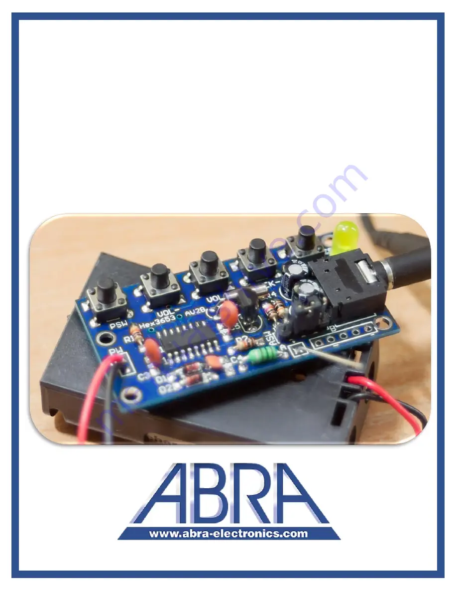
background image


HEX3653 FM Radio Receiver 

Module D.I.Y. Kit 


(for Advanced Users)


Part Number:


AK-270


Summary of Contents for AK-270

Page 1: ...1 HEX3653 FM Radio Receiver Module D I Y Kit for Advanced Users Part Number AK 270...

Page 2: ...2 Table of Contents 1 Description 3 2 Specification 3 3 Bill of Materials 3 4 Circuit Diagram 5 5 How It Works 6 6 Assembly 8...

Page 3: ...n receive modulated FM signals with a frequency range of 76 to 108MHz The integrated circuit of this module will allow you to increase decrease the volume seek channels on the FM band and use an exter...

Page 4: ...Axial Inductor L1 7 2x 1N4148 Switching Signal Diodes D1 D2 8 1x SS8050 NPN Transistor Q1 9 1x HEX3653 SOIC IC chip U1 10 1x 32KHz Round Crystal Y1 11 1x 3mm Yellow LED LED 12 1x 3 5mm Stereo Audio S...

Page 5: ...5 4 Circuit Diagram The following figure represents how the HEX3653 FM Receiver circuit is constructed...

Page 6: ...the antenna electrons in the antenna begin to vibrate up and down The antenna signal originates at the header pins Pin 1 on the header is for connection of an external antenna Pin 2 is connected back...

Page 7: ...s a 32KHz crystal connected to pin 9 RCLK The RCLK signal is controlled by the SEEK and SEEK push buttons The tuning detection and amplification of the signal is all done inside the HEX chip The audio...

Page 8: ...your small speakers or a headphone These audio signals are also connected to the through hole connectors labelled B on the circuit board so you can essentially integrate this module into other applica...

Page 9: ...values using proper equipment i e using a Digital Multimeter to verify the ohmic value of the resistors before proceeding to the next step You can also verify that the LED is functional before solderi...

Page 10: ...on the bottom side of the board ONLY FOR THROUGH HOLE COMPONENTS f Have a rosin flux pen or paste handy Adding flux to the pads before soldering the component makes the process easier by letting the m...

Page 11: ...acitors C3 C4 C5 the inductor L1 and the diodes D1 D2 on the board and solder them from the bottom side You can solder these through hole components one by one or all at once 8 Place the transistor Q1...

Page 12: ...o the board and solder the pins that are inserted in the square shaped pads There are five of them 12 Finally place the single row 4 pin header ASW on the board and solder it from the bottom side Reme...

Page 13: ...ve and the negative wires of the battery holder in the appropriate hole on the board PW and solder them from the bottom side Insert two AA 1 5V batteries 17 Place the header jumper between pin 2 and 3...

Reviews: