40
MAINTENANCE AND SERVICE
Troubleshooting
When a fault occurs, the information will be written on display and device will stop, if not
stop it yourself by main switch and disconnect it from main power supply. When device
malfunctions, disconnect the device from mains and call the authorized service - do not
repair it yourself!
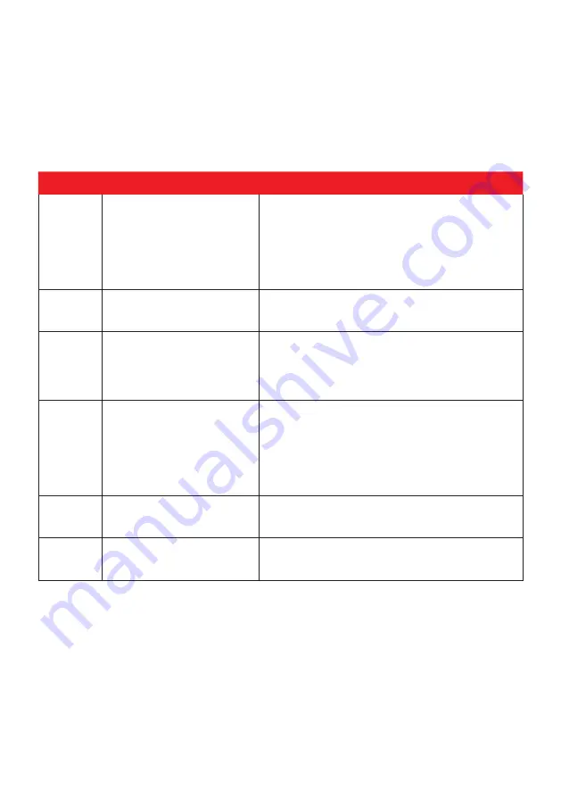
In the chart below are most common errors and resolutions
Error code
Description
Resolution
1
Device will not start, the
information on display is:
“Water low level”
There is not enough heating water inside the
device, add water – see chapter water filling into
secondary coat.
Water level sensor may be malfunction – authori-
zed personnel may check for loosened contacts,
for inappropriate position or may replace the
sensor.
2
Device will not start; the
display is blank
Check the main power supply
Check the main switch position
Check the safety stop button position
3
Device worked, then it sud-
denly stopped heating.
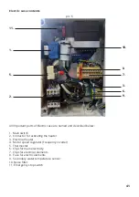
Authorized personnel may open electro case and
check the fuse state – see chapter with electric
case contents.
If the fuse is activated call authorized service to
check for electrical malfunctions.
4
Device worked, then it sud-
denly stopped heating.
Authorized personnel may open electro case and
check the thermostat state
– see chapter with electric case contents.
If the thermostat is activated the device has
overheated - call authorized service. The security
switch switched off all functions on the device.
(overheating protection).
5
“Error tmp. MILK” is shown
Milk sensor is malfunction – authorized personnel
may check for loosened contacts or replace the
sensor.
6
“Error tmp. WATER” is shown Heating water sensor is malfunction – authorized
personnel may check for loosened contacts or
replace the sensor.
Summary of Contents for Milky FJ 50 PF
Page 7: ...7 Bild 1 12 5 9 4 7 1 2 11 Bild 2 13 14 16 15 3 8 10 19 6...
Page 8: ...8 Bild 4 Auslass ist niedriger als Kesselboden Bild 3 PU Isolation 17 18 20 21...
Page 23: ...23...
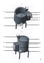
Page 29: ...29 pic 1 12 5 9 4 7 1 2 11 pic 2 13 14 16 15 3 8 10 19 6...
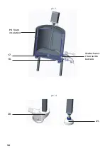
Page 30: ...30 pic 4 Outlet lower than kettle bottom pic 3 PU foam insulation 17 18 20 21...
Page 45: ...45...
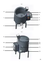
Page 51: ...51 Fig 1 12 5 9 4 7 1 2 11 Fig 2 13 14 16 15 3 8 10 19 6...
Page 52: ...52 pic 4 La sortie est au fond de la chaudi re Fig 3 PU isolation 17 18 20 21...
Page 67: ...67...

