18
J-300
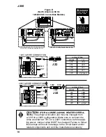
Figure D
(North American 60 Hz
120/240 VAC Convertible Models)
Green
TB3
TB1
A
B
C
D
OZONE
P1 1SPD
UV
A/V
30A
F2 10A 250VAC
F3 0.125A 240V
30A
FAN
STEP LIGHT
(OPTIONAL)
J37
J44
J73
J72
J74
J35
J59
J51
J33
J36
J46
J41
J47
J49
J38
J53
TB3
120 VAC 3-Wire connection 60 Hz
240 VAC 4-Wire connection 60 Hz
A
B
C
D
J37
J44
J73
J72
J74
J35
J33
J36
J46
J41
J47
J49
J38
J53
Wht Black
Green
TB3
OR
TB1
A
B
C
D
J37
J44
J73
J72
J74
J35
J33
J36
J46
J41
J47
J49
J22 240V
120V
120V
J38
J53
Wht
Blk
Red
J22 240V
120V
120V
TB1
TB1
GRN
BLK
WHT
120V 3-WIRE CONNECTION
240V 4-WIRE CONNECTION
J51
J33
1
2
3
4
J41
J47
J53
J38
J46
J36
J37
J59
GRN
WHT
BLK
RED
J51
J37
J59
A
B
C
D
240V
120V
120V
J22
240V
120V
120V
J22
J33
1
2
3
4
J41
J47
J53
J38
J46
J36
A
B
C
D
J22
120V
120V
240V
J22
120V
120V
240V
Jumper Wires
FROM
TO
J37
J36
J51
J46
J59
J41
J33
J47
J22
2 jumpers
Jumper Wires
FROM
TO
J37
J38
J51
J46
J59
J53
J33
J47
J22
1 jumper
CAUTION:
(FOR A 4-WIRE 240 VAC HEATER OPERA-
TION.)
The jumper at location J22 must be changed from
a 120V to a 240V configuration. Make sure to connect the
wires as shown at TB1, for a 240V connection, before apply-
ing power. Jumper wires MUST be changed. Failure to follow
these steps will result in damage to the circuit board and/or
related components and void the manufactures warranty.
DANGER
Turn power off
before servicing. This
task should only be
performed by a quali-
fied technician.
!
RISK OF SHOCK OR
ELECTROCUTION!
Summary of Contents for J - 375
Page 6: ...J 300...

