


PART
NUMBER
DESCRIPTION
SERIAL NUMBERS
100
3700
Strainer, 'Y', 3/4"
All
1
4000
Switch, rinse/fill (All) (SPDT) momentary slip disconnect
AF24, 451; 2618; 1149
1
0155500
Switch, manual wash (DPDT) (All) Slip disconnect
AF24, 451; 2618; 1149
1
0157500
Switch, master (DPST) (All) Slip disconnect (used on
wash, heat & conveyor on 39's)
AF24, 451; 2618; 1149; 1059
1
0157500
Switch, heat (DPST) (All) Slip disconnect
1149
1
0162500
Switch, start (SPDT) (All) Slip disconnect
1149
1
0165500
Terminal Board, 3 pole, complete
All
1
0166000
Terminal Board, 2 pole, 70 amp, with/mount channel
All
1
0167000
Terminal Board, 9 pole, complete slip terminal
1149
1
0169100
Thermometer, wash or rinse, standard
All
1
0170000
Thermostat, standard (use 0170018 or 0170023)
All
1
0170018
Thermostat, rinse, 180° fixed
1
0170023
Thermostat, wash, 150° fixed
1
0171300
Timer, 220V w/wires and mounting plate, 50 Cycle
(All 50 Cycle)
1
0171500
Timer, 220V w/wires and mounting plate
All
1
0172700
Timer Motor, 220V (for module type timer), 50 Cycle
(All 50 Cycle)
1
0173000
Timer motor, 220V (for module type timer)
All
1
0177500
Timer micro switches, plastic module type (for Eagle Bliss)
All
3
0180000
Track, standard, front or back (use 0180000)
All
1
0180000
Track, comer model, complete (convertible)
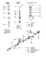
All
1
0182000
Vacuum breaker, poppet for 1/2" & 3/4" Febco (obsolete)
BF5490
1
0182500
Vacuum breaker, gasket for 1/2" & 3/4" Febco (obsolete)
BF5490
1
0183500
Vacuum Breaker, 3/4", Watts (use 0184301) (Conbraco)
AF13,034
1
0183501
Vacuum Breaker Repair Kit, 3/4", Watts (use 0184301
)(Conbraco)
AF13,034
1
0184300
Vacuum Breaker, 3/4" Sloan (use 0184301) (Conbraco)
WOO
Vacuum Breaker Kit (float & seal) 3/4'' Sloan
0185000
Valve, 1/4" (for Health Inspector's gauge)
All
1
0186500
Wash head cap w/race
AF19,035
2
0187000
Wash head cap set screw
AF19,035
2
0187500
Wash head center shaft
AF19,035
2
0188500
Wash head holding bolt
AF19,035
2
0044700
Wash head nut for holding bolt (nylon insert)
AF19,035
2
0193500
Wash head fixed race
AF10,282
2
0194000
Wash head bearings, 1/4", s/s
All
114
0194500
Wash head spray tube ONLY, long length
All
(as required)
0200000
WASH HEAD ASSY., UPPER & LOWER INTERCHANGE
All
2
0200500
Wash head, small manifold w/tubes
All
2
0201000
Wash head, large manifold w/tubes
All
2
0205000
Water level control, Curtis, 220V
AF23,344; 2526; All; All
1
0205500
Water level control, relay ONLY, Curtis
AR23,344; 2526; All; All
1
0206000
Water level control, printed board ONLY, Curtis
AF23,344; 2526; Ail; All
1
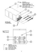
0009459
Rack support rod (Vee Shape) Rod only
0008201
Cantilever arm support bracket
0055001
Bottom front panel
0136700
Vertical feed pipe (inside tank) upper to lower rinse arm
0163700
Front door switch (some models) 3 terminal
0163800
Side door switch (some models) 6 terminal
0049801
Spacer Kit tor door wraparound
0138900
Rinse feed pipe support
6047603
Conversion kit straight-thru to corner
049800
Door wraparound
80001
Track rod support assembly
0058200
Heater element, flange tpe 208V, 1500W
0051900
Door plugs black plastic
6047100
Conversion kit corner to straight-thru
54
Summary of Contents for 100 B/PRB
Page 6: ......
Page 26: ......
Page 46: ...45 BOOSTER TANK HEATER ELEMENT P N 0060500 WASH TANK HEATER ELEMENT P N 0058000...