


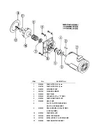

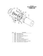


REPLACING SEAL and
CERAMIC on WASH PUMPS
FUNCTION
The pump is part of the total motor-pump system and utilizes one shaft seal and ceramic to prevent
the pump from leaking around the impeller and shaft. One gasket is used to prevent leakage between the
pump mounting plate and the machine pump plate.
REPLACEMENT OF SEAL AND/OR CERAMIC
1. Remove the power source to the machine by turning the circuit breaker to its "off" position on the side
of the control box.
2. Drain the machine by removing the overflow strainer in the wash tank.
3. Support the motor - - remove the four nuts holding the pump/motor to the machine's pump plate.
4. Carefully pull motor outward, move from side to side as required to remove from machine.
5. Set motor and pump on a sturdy stand close to machine or remove wires and conduit to allow
motor/pump to be moved to a better work station.
6. Insert a firm object into the blades of the fan and use a 5/16" ratchet to remove bolt holding impeller.
After the bolt is removed, pull the impeller up and off of the shaft.
7. The ceramic is imbedded in the pump mounting plate and usually does not need replacement, but the
seal normally would when water leaks around the motor shaft area. If replacement of either is
required, proceed as follows:
a. Remove the four bolts holding the pump mounting plate to the motor.
b. Slide the mounting plate up and off of the shaft and motor. The imbedded ceramic and
shaft seal will be removed with the mounting plate.
c. Turn over the plate and push the seal and/or ceramic out of the housing carefully. It
may be necessary to break the ceramic to remove it.
d. Clean the hole where the ceramic was installed.
e. Lightly coat with a lubricant around the new ceramic's edges and "0" ring. Gently press
the ceramic into place against the snap ring in the housing. Make sure that the grooved
side of the ceramic faces the motor and housing snap ring, leaving the smooth side toward
the impeller.
f. Make sure that the woodruff key is in place in the shaft and then set the plate back on the
motor over the shaft.
NOTE: A field tool can be made (to ease installation of seal) from a pipe or tube (3/4" CPVC typical
example) that has proper outside and inside dimensions. It must fit over step down in shaft, but be
close to larger shaft size on outside. To accommodate woodruff, cut long slot in tube. Lubricate tube
slip seal over tube onto shaft.
g. Lightly coat with a lubricant the new seal face and gently press it into place over the shaft
with the seal face against the ceramic. SEE NOTE ABOVE.
h. Place the spring over the shaft with the metal cap up. Press the impeller down onto the
shaft, aligning the keyway of the impeller with the woodruff key.
i. Tighten the impeller washer, lockwasher, and bolt into place. Replace the four bolts
that hold the mounting plate
to the motor.
8. Reinstall the pump and motor in the unit by reversing steps one through eight (it is suggested that a
new pump gasket be installed).
IMPELLER ROTATION:
WHEN FACING THE IMPELLER AFTER MOUNTING IT ON THE MOTOR SHAFT, THE
IMPELLER SHOULD TURN IN A CCW DIRECTION.
20
Summary of Contents for 100 B/PRB
Page 6: ......
Page 26: ......
Page 46: ...45 BOOSTER TANK HEATER ELEMENT P N 0060500 WASH TANK HEATER ELEMENT P N 0058000...