


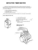


B. If heat relay closes:
1. Check power supply at incoming terminal board L1 and L2. It should be 220V, approximately.
2. Check power at positions 4 and 5, figure 1. Voltage should read approximately 220V; if not,
check wires for breaks or bad connections.
3. Check power at positions 6 and 7. Voltage should be approximately 220V. If not, check wires for
breaks or bad connections.
4. Temperature should rise
as
explained in A1 and amperages may be checked according to those
instructions. Replace any defective elements.
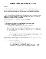
FIGURE NO. 1 RINSE HEATER SYSTEM
A. HEATER SWITCH
B. WATER LEVEL CONTROL
C. THERMOSTAT
D. HEATER RELAY
E. RINSE TANK HEATERS
F. AMPROBE TEST POSITION
X. TERMINAL BOARD (9 TERMINALS)
17
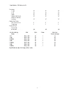
Summary of Contents for 100 B/PRB
Page 6: ......
Page 26: ......
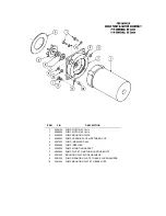
Page 46: ...45 BOOSTER TANK HEATER ELEMENT P N 0060500 WASH TANK HEATER ELEMENT P N 0058000...