I N I T I A L O P E R AT I O N
Page 23
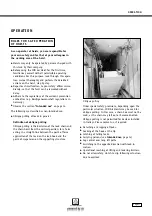
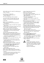
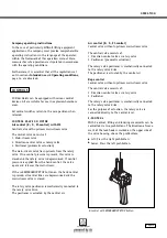
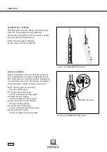
The control hoses for the drive motors (trolley/crane
movement) must be extended, outside of the bellows,
by means of plug-in connectors and additional control
hoses.
Connection
see "Trolley" operation manual.
AT T E N T I O N !
The control hoses must not be subject to
tensile load; adjust the strain-relief ropes
accordingly.
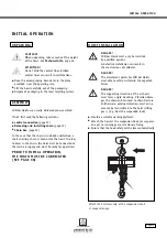
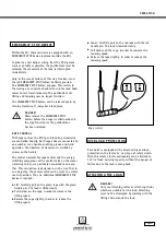
Pull the bellows over the hose adapter and secure via
the central bolt, (see illustration on page 22, bottom).
F I - CO N T R O L C O N N E C T I O N
Pull the bellows over the hose bundle for F-control.
Remove approx. 80 mm of hose bundle protective
sheathing.
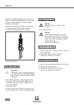
With this type of control, strain-relief of the hand
controls is via the protective sleeve of the hose bundle.
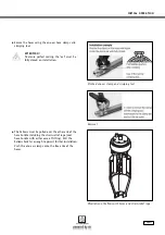
For this purpose, the protective sleeve is pushed onto
the hose carrier and is secured using a one-ear clamp.
Installation facilitation:
Heat the protective sleeve
(hose sheathing) with a hot-air gun and grease the
hose carrier.
Slightly bend open the ring of the eye bolt in order to
attach the hose carrier.
Close the ring again to prevent detaching.
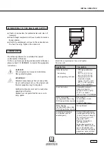
Insert the control hoses:
See illustration on page 22, top.
Compressed air
with hose designation 1 or colour: white
Movement direction "lift"
hose designation 2 or colour: green
Movement direction "lower"
hose designation 3 or colour: red
AT T E N T I O N !
The control hoses must not be subject
to tensile load; adjust the strain-relief
ropes accordingly.
Pull the bellows over the hose adapter and secure via
the central bolt, (see illustration on page 22, bottom).
If you wish to exchange air controls E, F or FI, proceed
as follows, (see illustrations in section Connecting the
controls)
C O N V E R S I O N F RO M E T O F
Control valve housing (on motor)
Removal of E-controls
Remove the hose adapter (secured by central bolt).
For removal of the hose adapter, a long A/F 6 socket
spanner must be guided through the middle of the bel-
lows and inserted into the hexagon socket of the bolt,
(illustration on page 22, below).
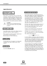
Pull the bellows back over the hose until the hose
nipples with the one-ear clamps are exposed and
further removal is possible.
Detach the strain-relief rope and remove the one-ear
clamps, (see illustration
Removal,
page 21).
Cut off the hoses below the hose nipples using a knife.
Unscrew the hose nipples (A/F 17).
Pull the bellows over the hoses of the E-controls.
This is also required for the F-controls.
Installation of F-controls
Pull the bellows over the hose bundle for F-control.
Remove approx. 80 mm of the hose bundle protective
sheathing or 160 mm for additional movements.
Screw the "straight screw connections" (Steck-fix) for
4 mm hoses into the hose adapter (A/F 16).
Pull the strain-relief ropes through the eye bolt and
secure using rope clamps.
Insert the control hoses:
See illustration on page 22, top.
Compressed air
with hose designation 1 or colour: white
Movement direction "lift"
hose designation 2 or colour: green
Movement direction "lower"
hose designation 3 or colour: red
R E P L AC I N G C O N T R O L S

