


16
Step 11. Connect the Speaker
Connect the speaker to the motherboard’s speaker connector. (Normally the
red cable is +5V power) (Reference to the Chapter 3—Hardware Installation
for detail pin assignment)
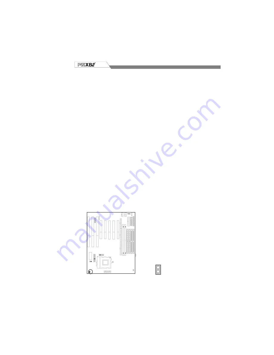
Step 12. Connect the Power LED
Most computer chassis provides a power LED for identify if the system is on
or off. Connect the power LED to the 2 pin pin-header motherboard’s LED
connector. (normally the red cable is +5V power)
Or connect to the left side of
onboard keylock .(Reference to the Chapter 3—Hardware Installation for
detail pin assignment)
Step 13. Connect the Devices LED
Some computer chassis provides device LED(Like HDD LED) for identify if
the device is under working or not. Connect the device LED to the
motherboard’s IDE device LED connector. (normally the red cable is +5V
power)
Step 14. Connect the Power Input
This motherboard provides two types of power input; the AT & ATX for
different choises.
The AT switching power provides 2 sets cable P8 & P9 (6 pin for each set)
and ATX power provides 1 set 20 pin cable for motherboard’s power input.
Step 15. Connect the ATX Power Switch
This motherboard provides a 2 pin connector for connecting a momentary
switch for the system on/off.
JP15
JP15
Summary of Contents for P55XB2
Page 2: ...2...
Page 8: ...8 75 90 100 120 133 150 166 180 200 233 266 JP7 JP4 JP3 JP16 JP15 Figure 2 Jumpers location...
Page 25: ...25 75 90 100 120 133 150 166 180 200 233 266 JP7 JP4 JP3 JP16 JP15 Figure 2 Jumpers for P55XB2...
Page 37: ...37 Parallel port is a 25 pins female external DB25 connector for parallel port PCI Parallel...
Page 88: ...88 MMX 200...