REL0.1
Page 7 of 95
Kintex Ult FPGA SOM Hardware User Guide
iWave Systems Technologies Pvt. Ltd.
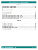
List of Figures
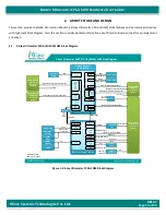
Figure 1: Kintex Ult FPGA SOM Block Diagram ................................................................................................................. 10
Figure 2: Kintex Ult FPGA Devices Comparison ................................................................................................................ 14
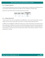
Figure 3: Indication LEDs .............................................................................................................................................................. 17
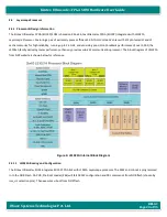
Figure 4: LS1021A Internal Block Diagram .................................................................................................................................... 20
Figure 5: Board to Board Connector1 ........................................................................................................................................... 27
Figure 6: Board to Board Connector2 ........................................................................................................................................... 41
Figure 7: Board to Board Connector3 ........................................................................................................................................... 62
Figure 8: Board to Board Connector4 ........................................................................................................................................... 73
Figure 9: Power Input Sequencing ................................................................................................................................................ 86
Figure 10: Heat Sink ..................................................................................................................................................................... 89
Figure 11: Mechanical dimension of Kintex Ult FPGA SOM - Top View ............................................................................. 90
Figure 12: Mechanical dimension of Kintex Ult FPGA SOM - Bottom View ....................................................................... 91
Figure 13: Mechanical dimension of Kintex Ult FPGA SOM - Side View ............................................................................ 92
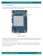
Figure 14 Kintex Ult FPGA (KU19P) Development Platform .............................................................................................. 94
List of Tables
Table 1: Acronyms & Abbreviations................................................................................................................................................ 8
Table 2: Terminology ..................................................................................................................................................................... 9
Table 3: Board to Board Connector1 Pinout ................................................................................................................................. 28
Table 4: Board to Board Connector2 Pinout ................................................................................................................................. 42
Table 5: Board to Board Connector3 Pinout ................................................................................................................................. 63
Table 6: Board to Board Connector4 Pinout ................................................................................................................................. 74
Table 7: LS1021A IOMUX on Kintex Ult FPGA SOM .......................................................................................................... 77
Table 8: Power Input Requirement ............................................................................................................................................... 85
Table 9: Power Sequence Timing .................................................................................................................................................. 86
Table 10: Temperature Specification ............................................................................................................................................ 88
Table 11: Orderable Product Part Numbers .................................................................................................................................. 93


