Original notice - A1.20
51
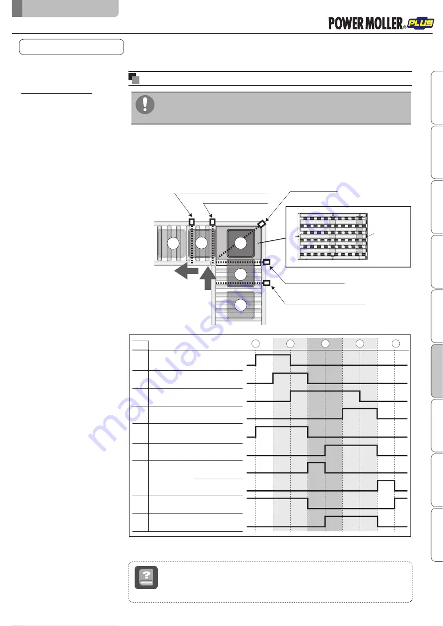
The following time chart is an example.
When in use, control the number of sensors, and/or determine how to place/control sensors
depending on your operation.
It is assumed that switches on CBK-109 and CB-016 are used based on the initial settings.
Zone sensor for the discharge conveyor
Area sensor for discharging
F-RAT zone sensor
Area sensor for loading
Zone sensor for the load conveyor
Time chart example
Tray position
Roller transfer MDR
㧔
M2
㧕
OUT1
(
Roller surface standby output
)
OUT2
(
Carrier wheel surface standby output
)
Carrier wheel transfer MDR
㧔
M1
㧕
Drive switching
MDR
㧔
M3
㧕
Area sensor for loading
1
2
3
4
5
ON
OFF
F-RAT zone sensor
ON
OFF
Area sensor for discharging
(
Carrier wheel discharge direction
)
ON
OFF
ON
OFF
ON
OFF
ON
OFF
ON
OFF
INPUT2
INPUT1
Carrier wheel surface
switch input
Roller surface
switch input
RUN
STOP
RUN
STOP
Zone sensor for the load conveyor
ON
OFF
Input
PLC
Input
Input
Input
Input
Input
Output
Output
Output
5
2
1
4
3
Basic operation
(example)
V-ribbed pulley
Operation by loading through
roller transfer and discharging
through carrier wheel transfer
Program example
When loading through roller transfer, discharging through carrier wheel transfer, and
standing ready on the roller surface after discharge ends
Program example
8-6.
Program example
■
Do not load trays from the roller transfer MDR direction while the carrier wheel
status (signal from CN2#2 on HBM-201) is output.
Failure to follow this could result in damage to trays, and malfunction.
*1
*1
*2
*1
*2
*1
*2
8.
Control/Operation
F-RAT-NX75 Technical document
Safety precautions
Advance preparation
Product check
Structures
Installation/Wiring
Control/Operation
Maintenance/Inspection
Tr
oubleshooting
Appendix
Zone sensor
Term
A sensor to detect the existence of trays within the zone
Area sensor
A sensor to detect load and discharge of trays


