Original notice - A1.20
50
PWR
ާ
Green
ި
STATUS
ާ
Orange
ި
ERR
ާ
Red
ި
INPUT1
Roller surface
switch input
OUT1
Roller surface
standby output
OUT2
Carrier wheel surface
standby output
INPUT2
Carrier wheel
surface switch input
( )
( )
( )
( )
( )
Output
Output
Input
Input
Run in the roller surface direction
Stop
Run in the carrier wheel surface direction
M3
㧦
Drive switching MDR
〔
M3:HBM-201
〕
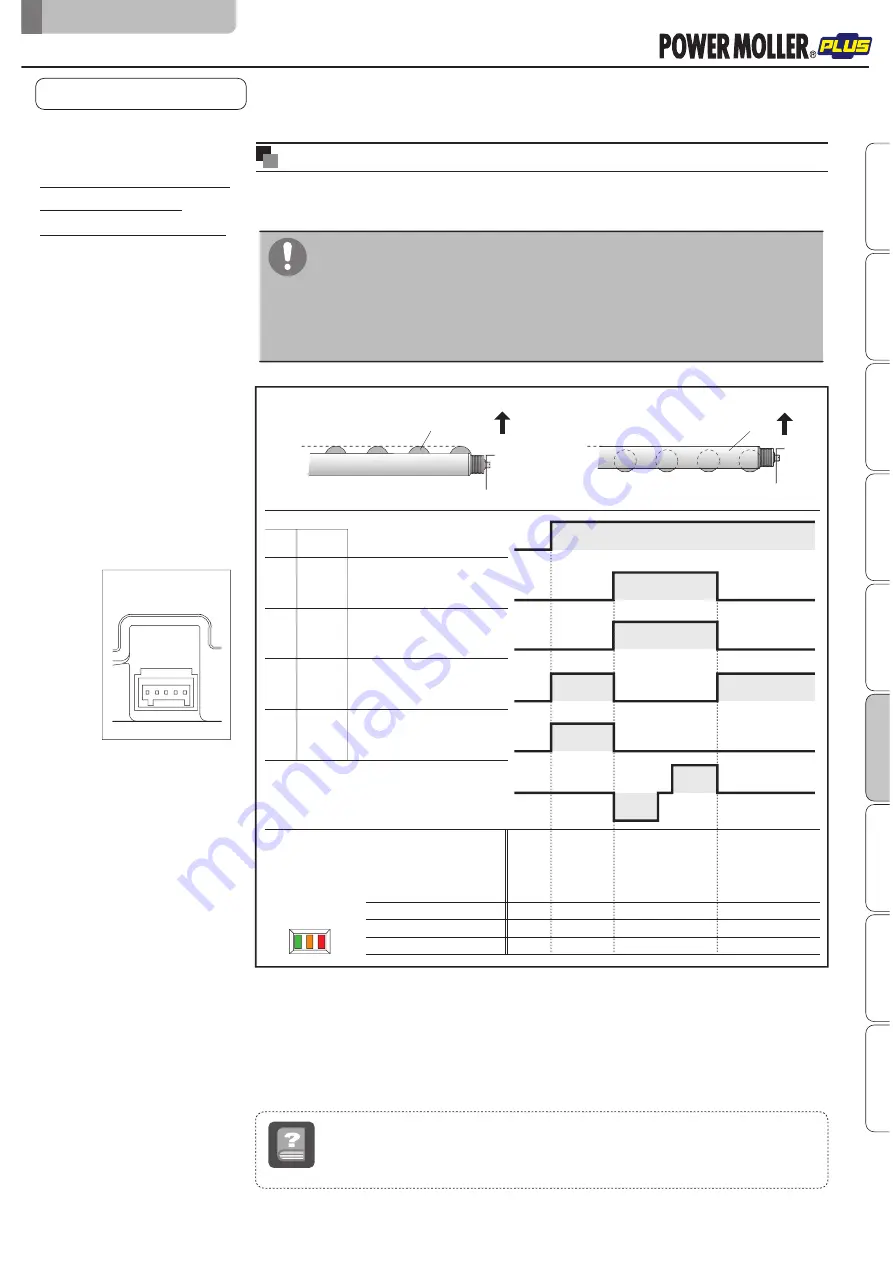
About the initial position setting (teaching) of the transfer surface
The initial position setting (teaching) of the transfer surface is necessary to set the
transfer surface after the power is turned on.
N/A INPUT1 INPUT2
OUT 1 OUT 2
PWR
ERR
STATUS
8-5.
About the initial position
setting (teaching)
of the transfer surface
Power
Transfer surface status
24V
0V
ON
OFF
ON
OFF
ON
OFF
ON
OFF
Power
OFF
Power
ON
Teaching operation
Teaching complete/
Roller surface
on standby
OFF
OFF
OFF
ON
ON
OFF
OFF
OFF
OFF
OFF
PLC
HBM-201
(
M3
)
CN2#4
Refer to CN2
CN2#5
CN2#1
CN2#2
Teaching operation
Carrier Wheel
Roller
teaching
■
If teaching has not been set, the transfer surface cannot be switched.
■
When teaching fails, both CN2#1(OUT1)(roller surface status output) and
CN2#2(OUT2)(carrier wheel status output) are turned ON, which is the same
status as when the power is turned on.
In such cases, perform teaching operation again.
8.
Control/Operation
F-RAT-NX75 Technical document
Safety precautions
Advance preparation
Product check
Structures
Installation/Wiring
Control/Operation
Maintenance/Inspection
Tr
oubleshooting
Appendix
preparing reception
complete
1Hz blinking
6Hz blinking
Teaching
Term
Operation to perform the initial setting of the transfer surface position.
After the power is turned on, perform teaching by inputting signal from the driver card.


