


Optidrive P2 Elevator User Guide V2.30
61
Parameters
www.InvertekDrives.com
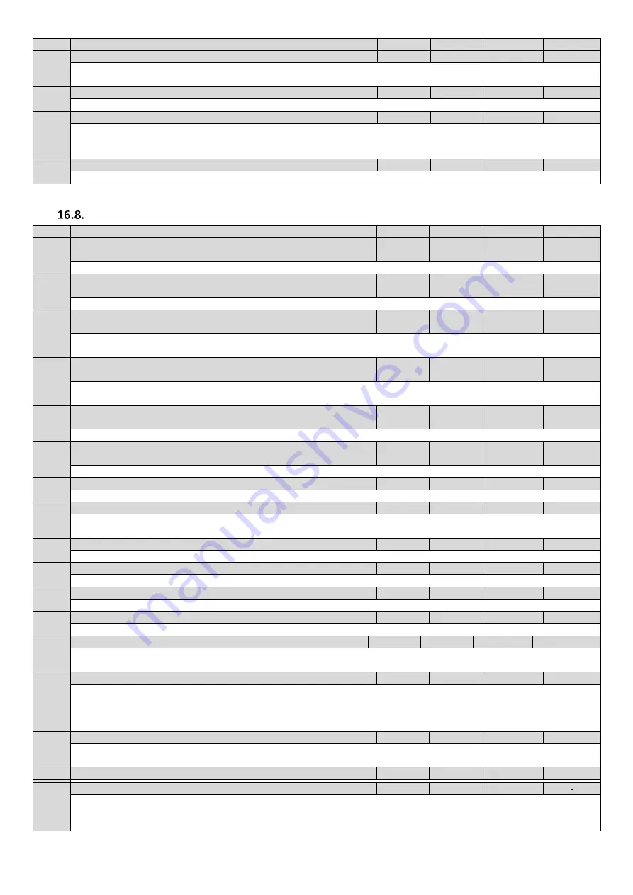
Par
Parameter Name
Minimum
Maximum
Default
Units
P6-27
Analog output 1 offset
-500.0
500.0
0.0
%
Defines the offset as a percentage used for Analog Output 1
Output value = (Input value - Offset) * Scaling
P6-28
P0-80 display value index
0
-
0
-
Internal use only. Only to be changed with guidance from technical support.
P6-29
Save User Parameters as default
0
2
0
-
Setting this parameter to 1 saves the current parameter settings as "User default parameters". When the User carries out a 3-button
default parameter command (UP, DOWN and STOP), the parameters saved when P6-29 was last set to 1 will be restored, Setting “2”
clears user parameters.
P6-30
Level 3 access code
0
9999
201
-
Defines the access code which must be entered into P1-14 to allow access to the Advanced Parameters in Groups 6 to 9.
Parameter Group 7:
Motor measured data, Rollback control gains.
Par
Parameter Name
Minimum
Maximum
Default
Units
P7-01
Motor Stator Resistance (Rs)
0.000
31.500
Rating
dependant
Ohm
For Geared (Induction) and PM motors: phase to phase rotor resistance value in ohms as measured following an Auto-tune.
P7-02
Motor Rotor resistance (Rr)
0.000
31.500
Rating
dependant
Ohm
For Geared (Induction) motors: phase to phase rotor resistance value in ohms as measured following an Auto-tune.
P7-03
Motor stator inductance (Lsd)
0.0000
1.0000
Rating
dependant
H
For Geared (Induction) motors: phase stator inductance value.
For Gearless (Permanent Magnet) motors: phase d-axis stator inductance in Henry (H).
P7-04
Motor Magnetising current (Id rms)
0.0
Rating
dependant
Rating
dependant
A
For Geared (Induction) motors only: magnetizing / no load current, before Auto-tune, this value is approximated to 60% of motor
rated current (P1-08), assuming a motor power factor of 0.8. Note: For gearless PM motors this value must be 0.
P7-05
Motor Leakage coefficient (sigma)
0.000
0.250
Rating
dependant
For Geared (Induction) motors: motor leakage inductance coefficient
P7-06
Motor stator inductance (Lsq) – PM motors only
0.0000
1.0000
Rating
dependant
H
For PM motors: phase d-axis stator inductance in Henry (H).
P7-07
Enhanced generator control
-
-
-
-
Internal use only. Only to be changed with guidance from Invertek technical support.
P7-08
Motor Auto-Pre torque
0
1
0
-
Provides a pre-torque value (prior to brake release), normally used to improve Gearless motor rollback if P7-13 limit has been
reached, and also helps reduce noise as a result of rollback function. Also Active in Rescue mode.
P7-09
Over voltage current limit
-
-
-
-
Internal use only. Only to be changed with guidance from Invertek technical support.
P7-10
System Inertia constant
0
600
10
System Load Inertia to Motor Inertia Ratio entered as H = (JTot/JMot) this value can normally be left at the default value (10).
P7-11
Pulse width minimum limit
-
-
-
-
Internal use only. Only to be changed with guidance from Invertek technical support.
P7-12
V/F mode/PM magnetising period
-
-
-
-
Internal use only. Only to be changed with guidance from Invertek technical support.
P7-13
Rollback Control Gain
0.0
400.0
0.0
%
Sets the Rollback gain value (Active during P3-07 brake release time). Increase to solve rollback, too high a value can cause
instability/Vibrations/Over current trips, See section 13.3 for full details. Also Active in Rescue mode.
P7-14
Low frequency torque boost
0.0
100
0.0
Not used when P4-01 = 2, Primarily intended for PM Motors operating in open loop.
Allows a Boost current to be applied at start-up and low frequency (limit defined by P7-15), as a % of the motor rated current (P1-
08). Injecting some additional current into the motor at low speed to ensure that rotor alignment is maintained, and improving
operation during starting and low speed.
P7-15
Torque boost frequency limit
0.0
50.0
0.0
Hz
Frequency range for applied boost current (P7-14) as a % of motor rated frequency (P1-09). This sets the frequency cut-off point
above which boost current is no longer applied to the motor.
P7-16
Reserved – Do not use
-
-
-
-
P7-17
Rescue Mode P-gain
0
400
10
-
Sets the proportional gain value for the speed controller during rescue Mode operation.
Too high a value can cause instability or even over current trips.


