


20
Optidrive P2 Elevator User Guide V2.30
Electrical Installation
www.InvertekDrives.com
Motor Holding Brake Control
The Optidrive P2 Elevator drive has been designed to control the holding brake on motors where a separate electromechanical brake is fitted.
The brake is controlled by the output relay (terminals 17 and 18) – see section 6.8 for details.
There are two different options for controlling the closing operation of the brake during stopping.
Motor Holding Brake control-Option 1
Closing the brake at a parameter adjustable output frequency level. This allows the brake to be signalled to close whilst the drive is
decelerating, allowing the user to preset the frequency so that the brake closes simultaneously when the output frequency reaches zero.
Related Parameters
Action
P3-07
(Brake Release Time)
P3-09
(Brake Apply Speed)
P3-10
(Zero Speed Holding
Time on disable)
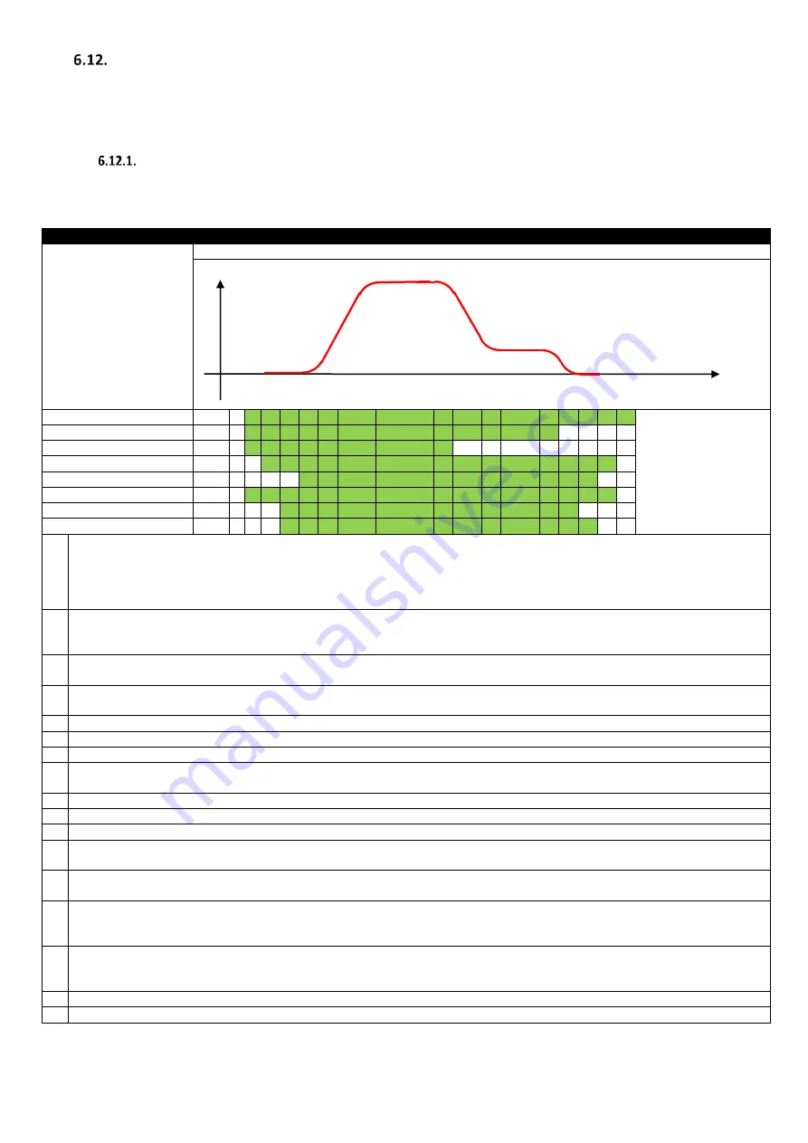
Program parameters as per the profile diagram below.
A B C D E F G H I J K L M N O P Q
STO Input
Enable & Direction Input
Run Speed Input
Drive Output Enabled
Output Frequency >0
Motor Contactor Output
Brake Control Output
Drive Enabled Output
A
STO Input Closed by external control system
Run Forward / Run Reverse input applied by External Control System
Run Speed (High Speed) Input Closed by External Control System
Motor Contactor Output (Relay 1) set by drive (to close motor contactor)
Drive waits for Output Contactor Closing time (P3-06) before enabling the output stage to drive the motor
B
After the Motor Contactor Delay time (P3-06) has elapsed, the Drive Output to the motor is enabled at zero speed
Drive holds zero speed on the output, and magnetises the motor (IM Motor)
For PM Motor, the magnetizing time is zero
C
After the Motor Magnetizing Time has elapsed, the motor brake control output (Relay 2) is set to release the motor brake
The output Frequency remains at zero until the Motor Brake Release Time (P3-07) has elapsed
D
After the Motor Brake Release Time (P3-07) has elapsed, the drive output frequency is ramped up.
The Ramp Rate is controlled initially using Acceleration S-Ramp 1 (P3-01)
E
The Acceleration rate is now controlled linearly by the Acceleration Ramp Parameter (P1-03)
F
As the Run Speed is approached, the acceleration is now controlled by Acceleration S-Ramp 2 (P3-02)
G
Operation at Run Speed (P2-02)
H
When the Run Speed Input is removed, the drive output frequency is reduced to the Levelling Speed (P2-01).
Deceleration is initially controlled by Deceleration S-Ramp 1 (P3-03)
I
After Deceleration S-Ramp 1 (P3-03) has completed, deceleration is controlled linearly by the Deceleration Ramp Parameter (P1-04)
J
As the output frequency approaches the Levelling Speed (P2-01), Deceleration S-Ramp 2 (P3-04) is applied
K
The drive operates at the Levelling Speed (P2-01) until the Direction Input is removed
L
On removal of the Direction input, the output frequency is reduced towards zero, with deceleration rate initially controlled by Levelling
S-Ramp (P3-05)
M
If the deceleration time is long enough to require linear deceleration, Deceleration Ramp Time (P1-04) is used
As the output frequency approaches zero, Levelling S-Ramp (P3-05) is again applied
N
When the output frequency reaches the Brake Apply Speed (P3-09), the motor brake control signal is removed to allow the motor brake
to close.
Output frequency continues to ramp towards zero speed, holding at zero speed.
O
After the Zero Speed Holding Time (P3-10) has elapsed, the drive output is disabled
For IM Motor control, a demagnetisation time is allowed for the motor prior to removing the Motor Contactor Output signal, allowing the
contactor to open. (This is not required for PM motors)
P
The Motor Contactor signal is removed allowing the contactor to open
Q
The STO Input to the drive can now be opened by the control system
Speed
Time


