


40
Optidrive P2 Elevator User Guide V2.30
Start-up of Gearless (Permanent Magnet) Motor-With Encoder Feedback.
www.InvertekDrives.com
Step 5- Motor Auto-tune.
A Motor Auto-tune must be carried out in order to measure the motor electrical characteristics, during the Auto-tune test the motor brakes
will be applied by the drive (assuming they are controlled by Relay 2 on the drive).
Action
Additional Information
If the motor contactor(s) are controlled by the elevator controller then they should be activated to close so that the motor is electrically
connected to the drive, otherwise the “Auto-tune” cannot be carried out.
If the motor contactor(s) are controlled by the drive (connected to relay 1) the motor contactor will automatically be energised when the
“Auto-tune” is enabled.
Note: For the motor contactor to close the safety chain will need to be closed.
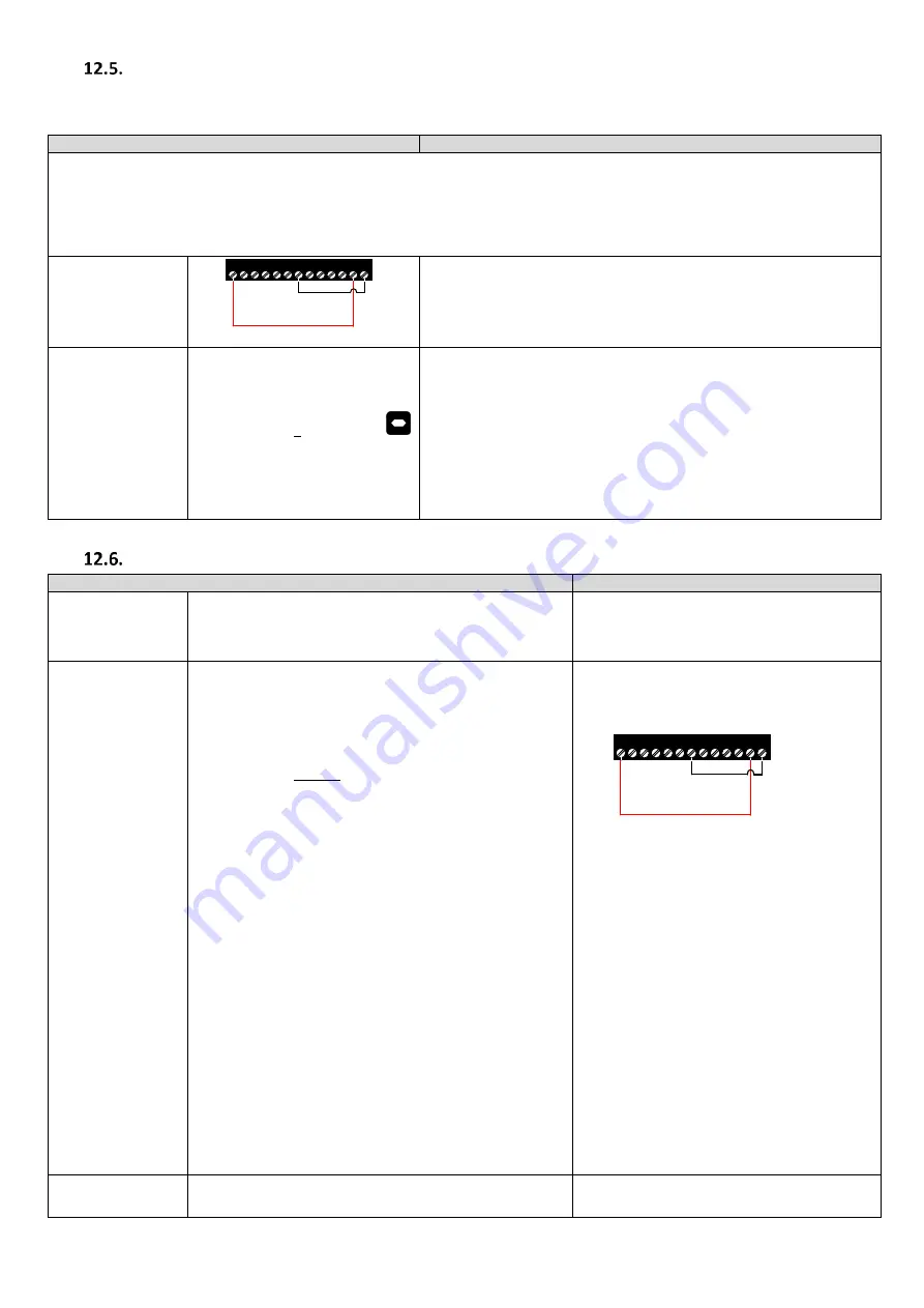
Check Safe Torque
off inputs have been
made.
1 2 3 4 5 6 7 8 9 10 11 12 13
Drive should now show
, if not see section 19 “Troubleshooting”.
Enable Motor Auto-
tune
Set P4-02 to a 1 and press the
button.
1.
The motor contactors will close (if controlled by the drive “Relay 1”).
2.
The motor brakes will remain applied.
3.
The display will show
. (Test procedure may take several
minutes to complete).
Once the Auto-tune is completed P4-02 will return to 0 and the display will
show
(P7-01/03/06 will be populated).
Note: Motor Auto-tune will need to be repeated if the motor, motor cables,
motor parameters or drive control mode is changed in P4-01.
Step 6- Encoder setup.
Action
Additional Information
Select absolute
encoder
(Endat or SinCos)
(P6-06)
Enter 65535 into P6-06
65535 value indicates that an Absolute
(Endat, SinCos) Encoder is being used.
Check motor
direction and
encoder direction is
correct.
Note : This step can
be skipped if motor
direction and
Encoder direction are
known to be correct)
Note: The below procedure should be performed with a no-load
condition (no ropes) or as close to a balanced situation as
possible, if this is not the case then the drive may show an error
message (“O-I” etc..) when commanded to run, furthermore
adjustment maybe required (i.e. increasing P7-14/P7-15) to
prevent “
” trips as per section 15 “Gearless (Permanent
Magnet) Motors-Without Encoder (P4-01=3).
Set P7-14 to 25% and set P7-15 to 10%.
During this check you will need to Navigate between
parameters P0-25 (Estimated motor speed) and P0-58 (Encoder
speed) on the drive keypad.
Provide a run-direction command to terminal 2 and run at
low speed (Levelling/10% rated speed) for a short travel, you
can Use P1-01 (Maximum speed limit) to limit the motor speed
and return back to normal value afterwards.
During travel Check that the value shown in P0-25 is positive
in the Up direction and Negative in the down direction, if it is
not then swap phase “V” and “W” and repeat the check.
Check that the value in P0-25 and P0-58 match in sign.
Stop the drive.
Set P7-14 and P7-15 back to 0%.
If the drive shows
when a run-
direction command is given ensure that the
Safe Torque off inputs are made.
1 2 3 4 5 6 7 8 9 10 11 12 13
If the motor does not operate as expected or
the drive shows an error message refer to
section 13 and section 19 “Troubleshooting“.
Enable the Encoder
(P6-05)
Set P6-05 to 1
Enables Encoder Feedback and puts the drive into
closed loop operation.


