


16
Optidrive P2 Elevator User Guide V2.30
Electrical Installation
www.InvertekDrives.com
Cables
For compliance with CE and C Tick EMC requirements, a symmetrical shielded cable is recommended.
It is recommended that the power cabling should be 4-core PVC-insulated screened cable, and laid in accordance with local industrial
regulations and codes of practice
The cables should be dimensioned according to any local codes or regulations. Guideline dimensions are given in section 18.3
Suitable fuses to provide wiring protection of the input power cable should be installed in the incoming supply line, according to the
data in section 18.3. The fuses must comply with any local codes or regulations in place. In general, type gG (IEC 60269) or UL type T
fuses are suitable; however in some cases type aR fuses may be required. The operating time of the fuses must be below 0.5
seconds.
Electrical Connections (Brake Resistor)
The drive has an internal brake transistor fitted as standard and is enabled automatically when the regenerative energy from the load raises
the drives internal DC bus to 390Vdc for the single and three phase 230V drives and 780Vdc for the 3 phase 400V drive.
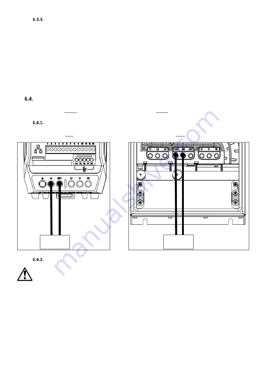
Connecting the brake resistor
The brake resistor should be connected between the +/+DC and BR Terminals of the drive as shown in the images below.
IP20
IP55
Braking Resistor
Braking Resistor
Brake resistor overload protection
From defaults the brake resistor overload protection is disabled.
Providing the correct values have been entered into parameters P3-13 and P3-14 the drive will protect the brake resistor against overload.
For correct protection:
Enter the resistance of the brake resistor in P3-13 (Ohms)
Enter the power of the brake resistor in P3-14 (kW)


