


Optidrive P2 Elevator User Guide V2.30
57
Parameters
www.InvertekDrives.com
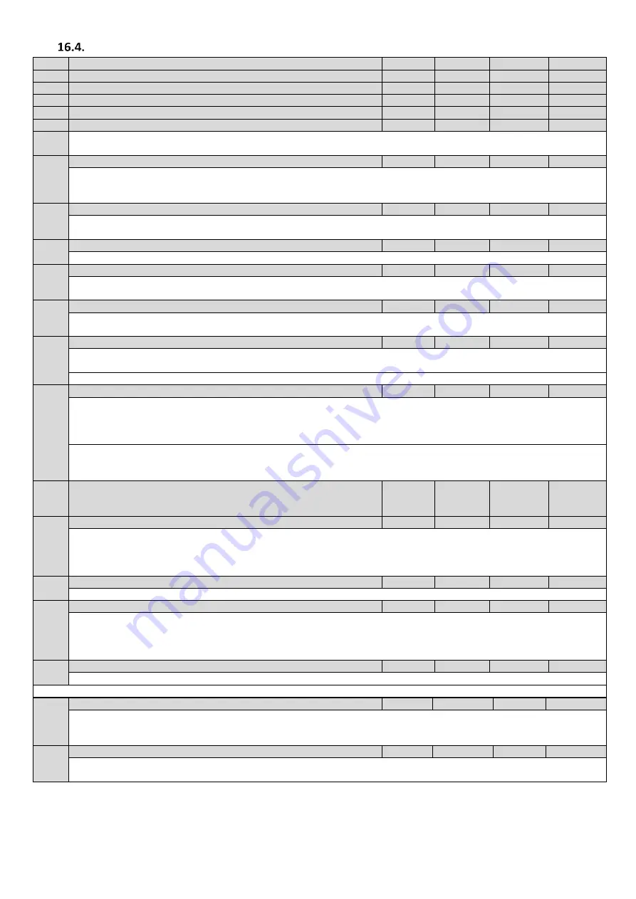
Parameter Group 3 –
S-ramps, Output contactor/Brake, Short floor, Light load detection.
Par
Parameter Name
Minimum
Maximum
Default
Units
P3-01
Acceleration Start Jerk
0.0
5.0
1.0
s
P3-02
Acceleration end Jerk
0.0
5.0
1.0
s
P3-03
Deceleration Start Jerk
0.0
5.0
1.0
s
P3-04
Deceleration end Jerk
0.0
5.0
1.0
s
P3-05
Stopping Jerk
0.0
5.0
1.0
s
S- Ramps are used to smooth the starting and stopping behaviour of the drive, refer to the diagram in section 13.1 for further
information on the operation of the S-Ramps.
P3-06
Output Contactor Closing Time/Run command delay time
0.00
5.0
0.2
s
Sets a delay time between the enable signal being applied to the Optidrive P2 Elevator drive and energising of the motor. This
prevents over current trips which may be caused when a contactor is installed between the Optidrive P2 Elevator drive and the motor.
The contactor can optionally be controlled by the drive using Output Relay 1.
P3-07
Brake Release time
0.0
2.00
0.50
s
Sets the delay time, following the contactor Delay time (P3-06) in which the motor brake will be released (Relay 2) and the drive
output frequency ramps up.
P3-08
Brake Apply Delay
0.00
2.00
0.20
s
Sets the delay time allowed for the motor brake to apply when stopping. (Motor brake control method 2 in section 6.12.2
P3-09
Brake Apply Speed
0.0
P1-01
0.0
Hz
Sets the speed at which the drive will signal the motor brake to apply. This speed must not be greater than the levelling &
maintenance speeds.
P3-10
Zero Speed Holding Time on disable
0.0
60.0
0.2
s
Sets the time for which the drive will hold the motor at zero speed prior to the output being disabled to allow the motor brake to
engage.
P3-11
Short Floor Operation
0
1
0
-
0 : Disabled
1: Enabled.
See section 14.1 Short Floor Operation for more detail
P3-12
Rescue Operation Function
0
3
0
-
0 : Basic Rescue mode
1 : Light Load Detection
2 : Reserved-Do not use
3 : UPS Easiest direction based on Load measurement
See section 14.2
Rescue Mode Operation (UPS Power Supply) for more details
P3-13
Brake Resistor Resistance
25.0
Drive
Rating
Dependant
Drive
Rating
Dependant
Ω
P3-14
Brake Resistor Power
0.0
200.00
0.00
kW
For software protection of the connected brake resistor, enter the rated power and resistance of the resistor into the relevant
parameters. The drive will then monitor the brake resistor to ensure that it does not operate outside of its designed limits.
Where an external thermal protection device is fitted, and software protection is not required. Setting parameter P3-14 to zero will
disable the software protection feature.
P3-15
Sheave diameter
0.0
2000.0
0.0
-
If value entered is <100 drive assumes inches, if >100 drive assumes mm
P3-16
Roping Ratio
1
4
1
-
1 : 1:1
2 : 2:1
3 : 3:1
4 : 4:1
P3-17
Gear Ratio
1.0
100.0
1.0
-
P3-15, P3-16 and P3-17 are used internally by the drive to provide elevator speed in user units as per section 9.7
Note: P1-10 must also be programmed for elevator speed in user units to operate.
P3-18
Motor Connected Check
0.0
100.00
15
%
At e
ach start, the drive injects a current pulse of this magnitude (% of motor rated current) to confirm that the motor is connected.
The default value rarely requires adjustment, the drive will trip “OUT-Ph” or “OUT-F” (Size 2) if the drive detects the motor is not
connected. See section 14.3 for more details.
P3-19
Torque Reduction during stopping
0.0
100
10.0
%
This parameter helps in reducing the noise in the lift car when the motor brake is closed due to the removal of current.
Increasing this value reduces audible noise, setting too high can result in reduced torque and rollback during stopping.


