


60
Optidrive P2 Elevator User Guide V2.30
Parameters
www.InvertekDrives.com
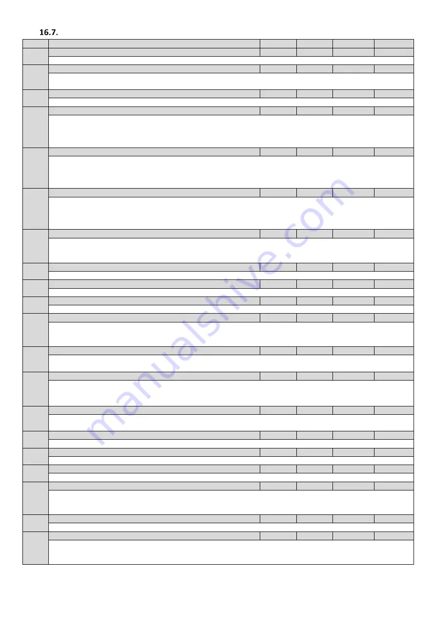
Parameter Group 6:
Encoder setup, Brake Release Monitoring,
Par
Parameter Name
Minimum
Maximum
Default
Units
P6-01
Firmware Upgrade Enable
0
3
0
-
Internal use only. Only to be changed with guidance from technical support.
P6-02
Auto thermal management
4kHz
12kHz
4kHz
kHz
This parameter defines the minimum effective switching frequency which the drive will use when the drive auto- switches down the
switching frequency in order to reduce the losses and heat from the power stage.
P6-03
Auto-reset delay time
1
60
20
s
Sets the delay time which will elapse between consecutive drive reset attempts when Auto Reset is enabled in P2-36
P6-04
User relay hysteresis band
0.0
25.0
0.3
%
This parameter works in conjunction with P2-11 and P2-13 = 2 or 3 to set a band around the target speed (P2-11 = 2) or zero speed
(P2-11 = 3). When the speed is within this band, the drive is considered to be at target speed or Zero speed. This function is used to
prevent “chatter” on the relay output if the operating speed coincides with the level at which the digital / relay output changes state.
e.g. if P2-13 = 3, P1-01 = 50Hz and P6-04 = 5%, the relay contacts close above 2.5Hz
P6-05
Encoder feedback enable
0
1
0
-
Setting to 1 enables encoder control mode of operation (Closed loop). For correct operation, ensure that the encoder has been
properly fitted to the motor and its wiring is connected to the encoder feedback module in accordance with the manual. Before
enabling this parameter, for Geared (Induction) motors run the drive in open loop mode (P6-05=0) and ensure that the sense of
rotation is correct by using parameter P0-58 (encoder feedback speed). The sign in P0-58 should match that of the speed reference.
P6-06
Encoder PPR
0
65535
0
-
Sets the number of Pulses Per Revolution for the encoder. This value has to be set correctly to guarantee proper operation of the
drive when Encoder feedback mode is enabled (P6-05 = 1). Improper setting of this parameter could cause the loss of control of the
drive and / or a trip. If set to zero, encoder feedback will be disabled. Typically values for Incremental encoders are 512, 1024, 2048,
4096, for Endat, SinCos Encoders 65535 must be entered.
P6-07
Speed error trip level
0.0
100.0
10.0
%
This parameter defines the maximum permissible speed error between the encoder feedback speed value and the estimated rotor
speed calculated by the motor control algorithms. If the speed error exceeds this limit, the drive will trip
.
When set to zero, this protection is disabled.
P6-08
Max speed ref frequency
0.0
20
0
kHz
0 (Disabled), 5kHz to 20kHz
P6-09
Encoder offset
0.0
360.0
0.0
°
PM Motors only : 0.0 …360.0° as measured by the stationary encoder offset measurement (P4-02=2)
P6-10
Enable PLC operation
0
1
0
-
0: Disable 1: Enable
P6-11
Brake Release-monitoring terminal Enable
Off
t18t19
Off
-
OFF: Brake release monitoring Disabled.
din-1…din-5
t18t19: T18 & T19 of Encoder module (OPT-2-ENDAT2-IN/ OPT-2-SINCOS2-IN) used for monitoring brake micro switches.
P6-12
Brake Release- monitoring time
0.1
5.0
0.5
s
If the monitoring terminal has not changed state in this time then the drive will trip “
" or “
" (if number of attempts as
set in P6-13 has been met) See section 14.4.
P6-13
Brake Release-number of errors before lockout
0
5
0
-
Number of brake release monitoring errors before permanent trip “
” is displayed.
If Parameter P2-36 is set to
then the drive will automatically reset the “
" message, otherwise the trip will have to
be reset manually e.g. Enable/direction input toggled.
P6-17
Max Torque limit timeout
0.0
25.0
0.0
s
Sets the maximum time allowed for the motor to be operating at the motor/generator torque limit (P4-07/P4-09) before tripping.
This parameter is enabled only for vector control operation.
P6-18
DC injection braking voltage
0.0
30.0
0.0
%
Auto, 0.0..25.0% (V/F mode only)
P6-22
Reset cooling fan run-time
0
1
0
-
Setting to 1 resets internal Fan run-time counter to zero (as displayed in P0-35).
P6-23
Reset kWh meter
0
1
0
-
Setting to 1 resets internal kWh meter to zero (as displayed in P0-26 and P0-27).
P6-24
Service time interval
0
60000
0
h
Defines the service interval counter period. This defines the total number of run time hours which must elapse before the service
indicator is shown on the drive (OLED/Optipad) display.
When P6-25 is set to 1, the internal service interval counter is set to this value.
P6-25
Reset service indicator
0
1
0
-
When this parameter is set to 1, the internal service interval counter is set to the value defined in P6-24
P6-26
Analog output 1 scaling
0
500.0
100.0
%
Defines the scaling factor as a percentage used for Analog Output 1
Output value = (Input value - Offset) * Scaling


