29
INSTALLATION AND ASSEMBLY
29
iV-Light ventilation unit | Installation instructions
►
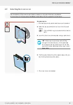
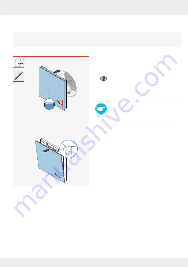
Pull the panel forwards at the upper edge until you
feel locking hook snap into place.
►
Slide the pre-assembled inner cover into the wall
sleeve.
The inVENTer logo is located at the bottom
right.
►
Level the inner cover base plate using a spirit level.
TIP:
If the inner cover does not sit firmly
enough in the wall sleeve, it can optionally
be screwed onto the interior wall. To do this,
use the 4 corner drill holes in the inner cover
base plate.
The inner cover is installed.
4.9 Installing the inner cover
The installation of the interior termination variants is not part of this documentation!
It can be found in the separate installation instructions for the respective component.
Requirements:
• The thermal accumulator insert has been installed.
!
Summary of Contents for 1001-0200
Page 1: ...www inventer de Installation instructions iV Light ...
Page 37: ...37 WARRANTY AND GUARANTEE 37 iV Light ventilation unit Installation instructions NOTES ...
Page 38: ...38 WARRANTY AND GUARANTEE 38 iV Light ventilation unit Installation instructions NOTES ...
Page 39: ...39 WARRANTY AND GUARANTEE 39 iV Light ventilation unit Installation instructions NOTES ...


