20
INSTALLATION AND ASSEMBLY
20
iV-Light ventilation unit | Installation instructions
X
in [mm]
=
Y
in [mm]
=
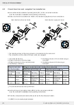
Inner cover
External termination
Light
Connect AP
Connect UP
Undercover
Standard
A + B + C + D
A + B + C + D - 38
10
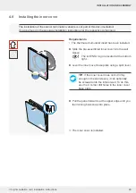
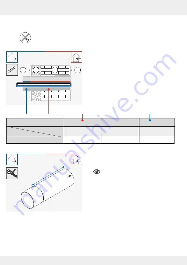
4.4 Installing the wall sleeve
Measuring tape, angle grinder, spirit level, non-pressing 2K polyurethane foam, cutter,
mounting wedge set and styrofoam discs
Requirements:
•
The wall opening Ø 180 mm is finished.
• The cables to the wall opening of the ventilation unit
have been laid.
X = ?
Y
D
A
B
C
►
Determine the exact wall thickness X:
D = Exterior rendering, incl. other superstructures
if applicable.
C = Insulation, if necessary incl. air gap
B = Masonry, incl. relining if necessary
A = Interior plaster
Y = Protrusion of the wall sleeve in the outer
area (depending on the installation situation
exterior rendering or masonry)
►
Cut the wall sleeve to the
determined dimension
X +
a protrusion of Y
on the exterior wall.
Be careful not
to cut away the cut-out for
the ventilation unit connecting cable.
X
+ Y
!
Summary of Contents for 1001-0200
Page 1: ...www inventer de Installation instructions iV Light ...
Page 37: ...37 WARRANTY AND GUARANTEE 37 iV Light ventilation unit Installation instructions NOTES ...
Page 38: ...38 WARRANTY AND GUARANTEE 38 iV Light ventilation unit Installation instructions NOTES ...
Page 39: ...39 WARRANTY AND GUARANTEE 39 iV Light ventilation unit Installation instructions NOTES ...


