


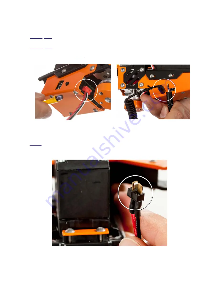
2.3.3 Camera trigger connection
For infra-red camera triggering connect the IR transmitter to the micro-match connector
(
Fig. 1-G
/
Fig.8
). Alternatively, for wire triggering use a cable that matches you camera type and has
a 2.5 mm jack on the other end. This cable should be connected to the input on the side
(
Fig. 1-H
/
Fig.8
).
Please make sure the appropriate camera triggering option (cable/infra-red) is
enabled in your camera
– refer to your camera manual. Later you will need to enable the
triggering option in the GUI (
Tab.3
).
Fig. 8
Camera triggering outputs
2.3.4 Power connection
A soldering job is needed to connect the female side of the mini-T power connector
(
Fig 1.-
L
)
with the supply of your helicopter.
Make sure to disconnect the battery while soldering
.
When the soldering is done, connect the mini connectors. Now you can plug the main battery
connector to power your multirotor and Pano360.
Fig. 9
Mini-T connector used to power Pano360
Micro-match connector
for IR camera trigger
2.5 mm Jack connector for
cable camera trigger
Mini power connector


