


Below are 3 examples of how the overcurrent protection works.
Fig.17
Overcurrent protection examples
3.2.3. Stop Detection
Note:
do NOT change this parameter if you have no prior experience. Before changing this
parameter make sure you read and understand this chapter.
Fig. 18
– Default stop detection settings
Stop detection (
Fig. 11-B
) is a function that tells the driver when the rotation comes to a
stop. Stop detection allows the driver to tell when to make a stop at each step.
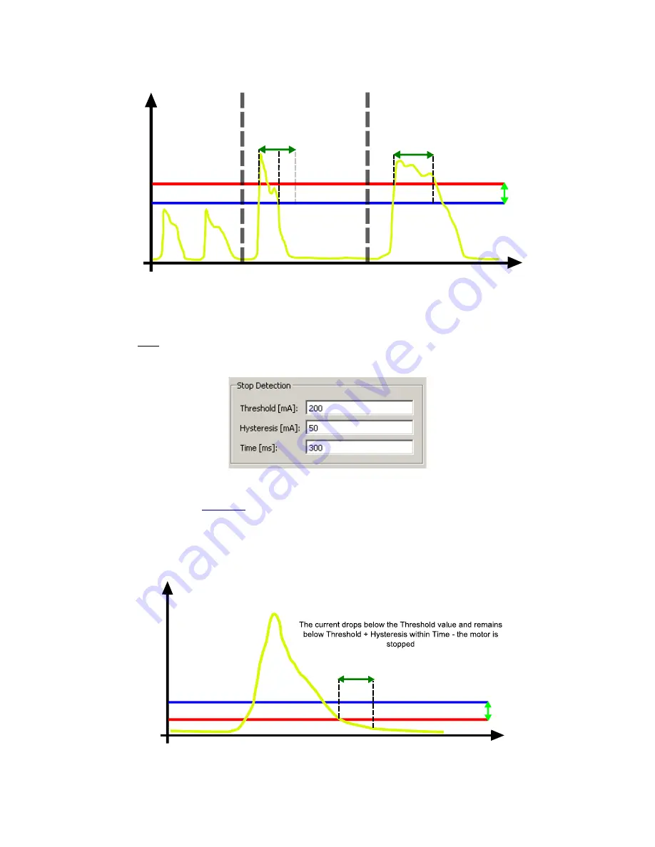
If, during
operation, the current drops below the Threshold value and remains below Threshold plus
Hysteresis within Time, then the controller assumes that the motor has stopped.
Fig. 19
Stop detection example
time [s]
cu
rr
en
t
[
A
]
Threshold [mA]
Time limit[ms]
Time Limit[ms]
1. Current is below the
threshold value, the motor
will NOT be turned off,
2. Current is above the threshold
value, but the current value minus
hysteresis is not within the time limit,
the motor will NOT be turned off
3. Current is above the threshold
value and the current value minus
hysteresis is within the time limit,
the motor will be turned off
Threshold - Hysteresis [mA]
H
ys
te
re
si
s
[mA
]
time [s]
cu
rr
en
t
[A
]
Time [ms]
Thr Hysteresis [mA]
H
ys
te
re
si
s
[m
A]
Threshold [mA]


