background image

3.3 Making user presets

Presets are user settings that help make great photos every time you launch the panoramic

sequence. The parameters ensure a consistent result for all the photos that are captured during
flight. Let's go quickly through all the parameters:
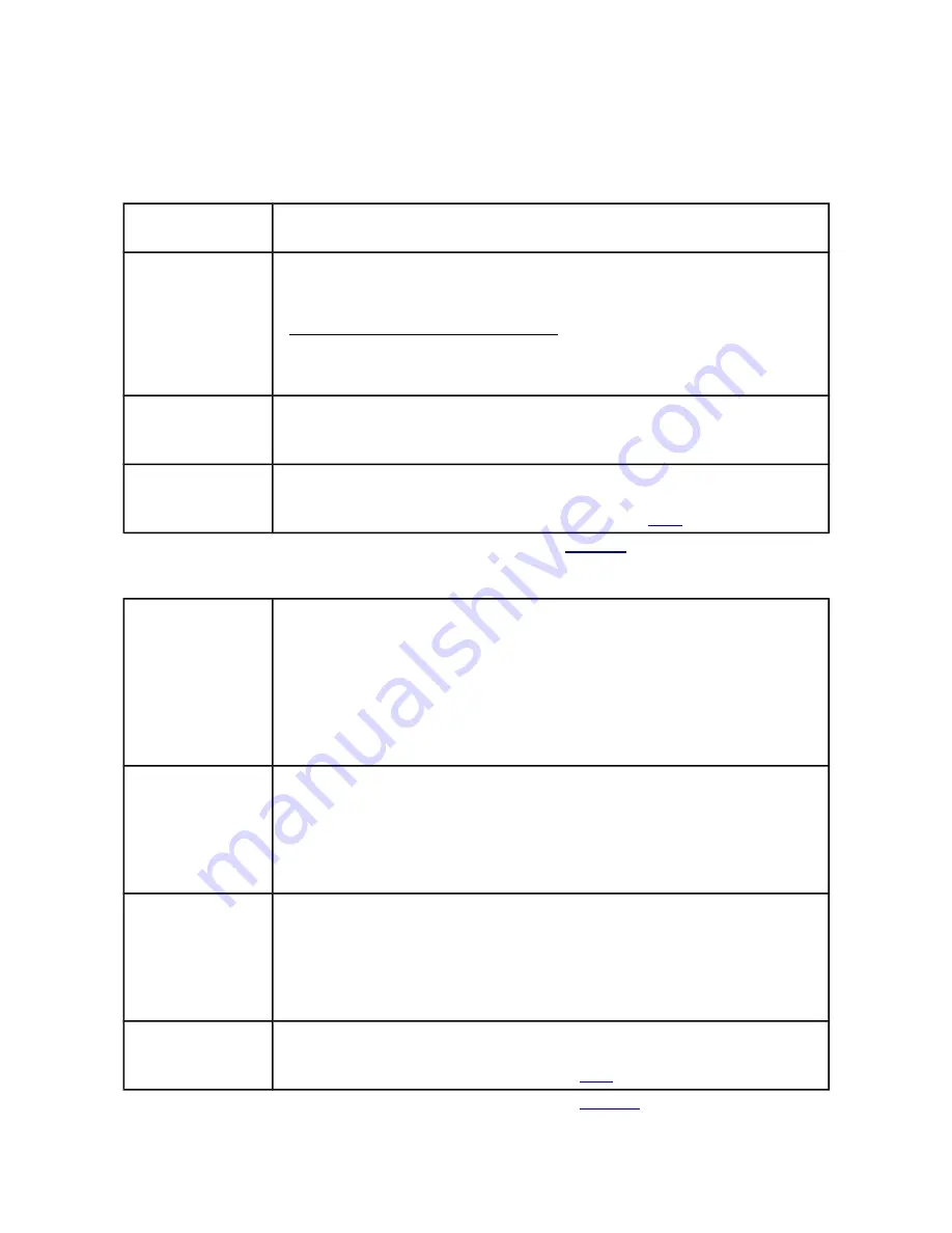
Name

Preset name, any set of 16 characters to name the preset. The name is displayed in 

the panel, which allows an easier identification.

Number of steps

This parameter defines the number of camera stops to be made for each panoramic

sequence. The whole sequence is evenly divided by the number of steps. 

Think of

this parameter as a number of grooves in a detent ring of a panoramic rotor

.

Angle of the whole panoramic sequence

[

°

]

Number of steps

=

Angle of rotationbetween stops

[

°

]

For example: if the panoramic sequence has a 360°degree turn, the number of 

steps set to 4 will result in stop at each 90°(360°/4=90°).

Photos per step

The number of photos to be made at each step. Each photo will be using the same

Camera   Release   parameters   (Autofocus   Delay/Autofocus   Time,   Shutter   Delay,
Shutter Time). 

Manual control

If the box is checked then the manual control is active, this means the rotation is
controlled by hand with a joystick. 

Make sure you connect Pano360 properly for this mode (

Fig. 7

)

Tab. 1 

General option for presets (

Fig. 11-E

)

Acceleration [°/s ²]

The rate of increase in speed from 0  to  Max Speed. Lower values will result in a
more smooth, sluggish operation – recommended for higher payloads. Higher value

will result in a more speedy/aggressive operation – recommended if the payload is
small and fast operation does not make the multirotor swing in the air.

Value range: 0-9999, 

Acceleration = 1 - minimum acceleration

Acceleration = 9999 - second highest acceleration

Acceleration = 0 - maximum acceleration 

Deceleration [°/s ²]

The rate of decrease in speed from Max. Speed to 0. Lower values will result in a
more slower operation. Higher value will result in a more faster operation.

Value range: 1-9999

Deceleration = 1 - minimum deceleration

Deceleration = 9999 - second highest deceleration

Deceleration = 0 - maximum deceleration 

Max Speed [°/s ]

The maximal angular speed of the movement.  Lower values will result in a more
slower operation. Higher value will result in a more faster operation.

Value range: 1-9999

Deceleration = 1 - minimum value of Max Speed

Deceleration = 9999 - second highest value of Max Speed

Deceleration = 0 - maximum value of Max Speed 

Stop time [ms] 

/

 Use stop detection

Stop time defines the time the motor needs to make a full stop between the steps.
If “Use  stop detection” is  activated  this  setting is  inactive and  the full  stop is

determined based on Stop Detection settings (

3.2.3

).

Tab. 2 

Kinematics options for presets (

Fig. 11-F

)

Summary of Contents for Pano360

Page 1: ... 1 Servo connection 5 2 3 2 Digital input connection 5 2 3 3 Camera trigger connection 7 2 3 4 Power connection 7 2 3 5 Pano360 PC connection 8 3 Pano360 GUI 8 3 1 Quick example on how to set the parameters in Pano360 GUI 9 3 2 Global settings 10 3 2 1 Servo Pulse 10 3 2 2 Overcurrent Protection 11 3 2 3 Stop Detection 12 3 3 Making user presets 13 4 Character display information 15 5 Additional i...

Page 2: ... this is useful for mounting Pano360 on a tripod or connecting it with a panorama head other than Nodal Ninja C custom servo motor D cable camera shutter and auto focus output 2 5 mm jack socket E Pano360 PC communication micro USB socket F mounting hub for Nodal Ninja Ultimate R1 R10 or UNC thread plate G wireless camera shutter control infra red transmitter connector H servo motor output 3 pin h...

Page 3: ...or refer to 2 2 3 Connect the cables refer to 2 3 4 Configure the device parameters and make a test run refer to 3 5 Configure your RC radio transmitter please refer to the manual of your transmitter 2 1 Software installation Let s start with software installation The latest software can be found here www invendyne com Download InvendynePano360Setup exe Run InvendynePano360Setup exe double click t...

Page 4: ...inja comes with a set of M5 screws it is best to use this screws to mount the tilt head to the hub Fig 3 Pano360 with Nodal Ninja To mount Pano360 to DJI H frame it is best to remove the carbon pipes and slide them once again through all DJI elements and Pano360 rubber grommets Fig 1 A Fig 4 Pano360 mounting to DJI H frame Nodal Ninja UNC adapter ...

Page 5: ...s powered can damage the pano360 and or the radio receiver 2 3 1 Servo connection Start by making sure the servo motor Fig 1 C cable is properly connected to the servo output Fig 1 H The white cable should be facing inward and all the pins should be connected Fig 4 Servo cable connection 2 3 2 Digital input connection There are two modes of operation automatic and manual For each mode you will be ...

Page 6: ...l input Fig 1 I Fig 7 and the 2nd digital input Fig 1 J Fig 7 Fig 7 Manual mode connection example At this point you may want to bind your RC receiver with the RC transmitter if you haven t already done so Do configure your RC transmitter to trigger the channels that correspond to Pano360 inputs Please refer to your transmitter manual for more information on how to setup the channels for your RC t...

Page 7: ...efer to your camera manual Later you will need to enable the triggering option in the GUI Tab 3 Fig 8 Camera triggering outputs 2 3 4 Power connection A soldering job is needed to connect the female side of the mini T power connector Fig 1 L with the supply of your helicopter Make sure to disconnect the battery while soldering When the soldering is done connect the mini connectors Now you can plug...

Page 8: ...rent parameters of the device Below is a quick overview of the program Fig 11 Pano360 GUI overview Micro USB connector A Parameters which are used to protect the motor and controller from damage B Parameters which are used to determine when the motor has came to a stop C These parameters determine the rotation angle and the shaft position D Preset list preset order setting E Parameters that tell h...

Page 9: ...offset for now the default values might not be ideal but they should be pretty close Select Default 1 in the Preset list Fig 11 D Fig 12 Choosing presets for editing from the preset list in Pano360 GUI Set the values of General Kinematics and Camera Release for the Selected Preset as shown below Fig 13 A quick example on how to setup the Pano360 parameters Click the bottom Apply button in the Sele...

Page 10: ...usted every time you decide to detach the collet from the shaft or the belt skips Servo pulse can be changed within 750 2250 µs range It is best to start with home location set to 1400µs Enter 1400µs value as Home Location and click Apply in the Global Settings section to confirm Depending on your needs the shaft camera front angle can be adjusted For example if you want the shaft to rotate clockw...

Page 11: ...raws high currents when a the drive gets blocked this usually happens when the camera hits the landing gear during operation or something gets stuck between the pulleys and the belt b the load is high and the driving parameters are too aggressive a heavy camera is used and the Acceleration and Max Speed parameters Tab 2 are too high for the load Pano360 electronics has the ability to detect high c...

Page 12: ... current drops below the Threshold value and remains below Threshold plus Hysteresis within Time then the controller assumes that the motor has stopped Fig 19 Stop detection example time s current A Threshold mA Time limit ms Time Limit ms 1 Current is below the threshold value the motor will NOT be turned off 2 Current is above the threshold value but the current value minus hysteresis is not wit...

Page 13: ...mode Fig 7 Tab 1 General option for presets Fig 11 E Acceleration s The rate of increase in speed from 0 to Max Speed Lower values will result in a more smooth sluggish operation recommended for higher payloads Higher value will result in a more speedy aggressive operation recommended if the payload is small and fast operation does not make the multirotor swing in the air Value range 0 9999 Accele...

Page 14: ...is preceded by Shutter Delay Value within the range of 0 9999 ms Fig 20 Value 0 disables Shutter Time Wait Time ms An amount of time before the next step or next photo after Shutter Time and Autofocus Time have ended This parameter is useful when you want to allow extra time for your SD card to save a photo Fig 20 Tab 3 Camera release options for presets Fig 11 G The total step time consists of St...

Page 15: ...s used with aggressive acceleration max speed and deceleration parameters If you are using a high payload make sure to adjust the overcurrent protection or lower the Acceleration Deceleration and Max Speed Values Fig 11 E to enable slower camera movement Letter L bootLoader the bootloader is active The device is updating the firmware Letter A stop detection is in progress the controller is waiting...

Page 16: ...s User s Manual and reserves the right to make improvements to this User s Manual and the product described in this User s Manual at any time without notice If you find information in this manual that is incorrect misleading or incomplete we would appreciate your send us comments and suggestions to contact invendyne com Acknowledgement This product was developed using ChibiOS 2 6 5 real time opera...

Reviews: