Invacare LiNX REM400 User Manual Download Page 48

60126081-C

47

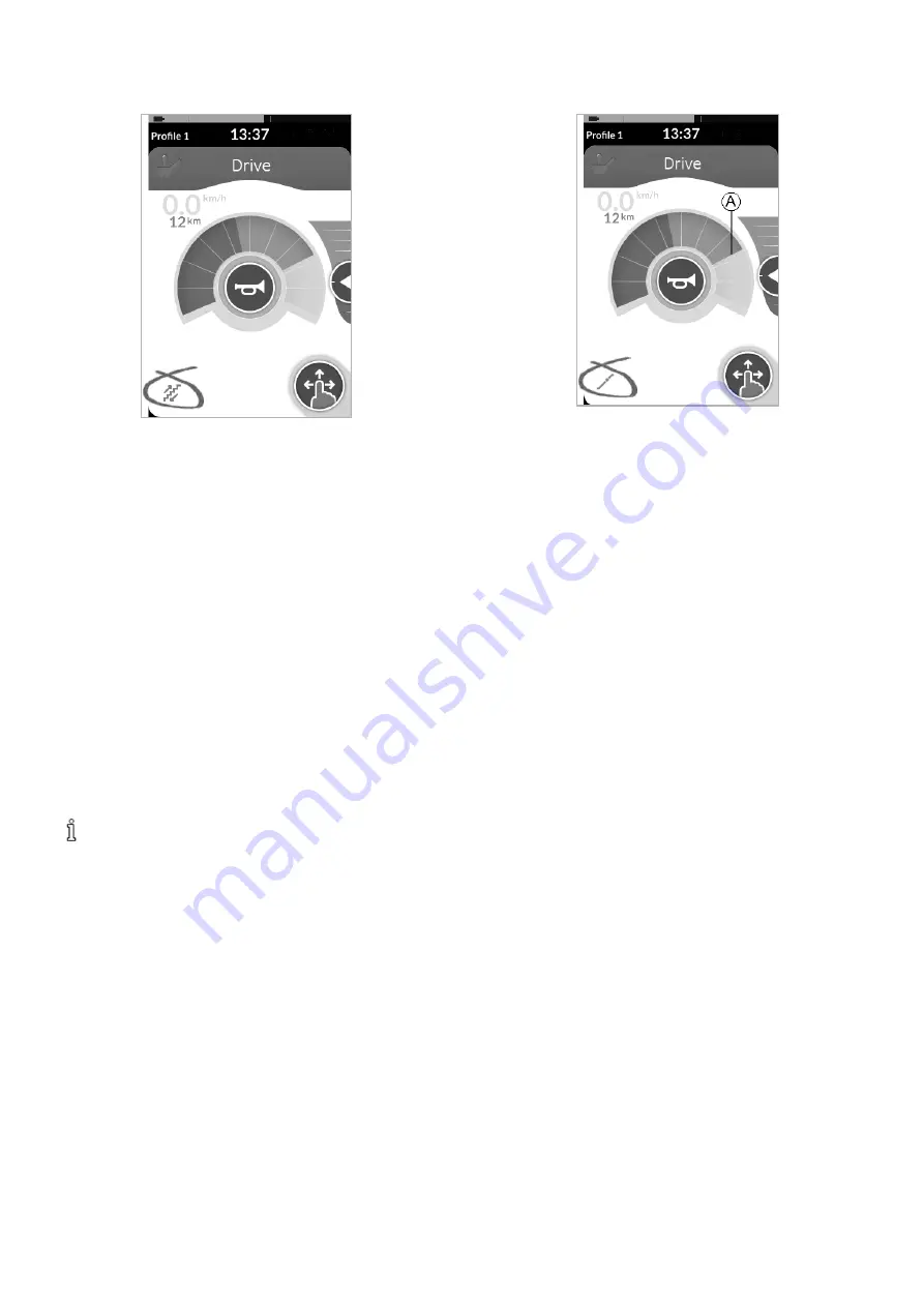
6.6.7  5 Step Up/Down

In this mode, you can step up or down through one of five fixed
 speeds. The speeds available are 20%, 40%, 60%, 80% and 
100% of the maximum preset reverse or forward speed 

A

 of 

the selected drive screen. The speed is maintained for the 
programmed Latch Drive Timeout period as long as no further 
command is given.

Driving

 1.  Give  a  drive  command  in  the  desired  direction 

(forward  or  reverse).

 2.  Release the drive command. The wheelchair speed 

accelerates to 20% of the maximum drive speed.

 3.  Give a forward command when driving forward or a 

reverse command when driving in reverse to accelerate to 
the next fixed higher speed.

 4.  Give a reverse command when driving forward or a 

forward command when driving in reverse to decelerate 
to the next fixed lower speed.

The drive command in the opposite direction must be  
less than one second; otherwise, the wheelchair stops.

 5.  Release the drive command. The new speed is held 

constantly.

Stopping

Use one of the following methods to stop:


l

Give a drive command longer than one second in the 
opposite direction (a reverse command when driving 
forward or a forward command when driving in reverse)


l

Press the external stop switch


l

Perform an emergency stop


l

Let the Latch Drive Timeout expire

6.6.8  Cruise Control

In this mode, you do not have fixed steps and can choose the 
latched speed yourself. The speed is maintained for the 
programmed Latch Drive Timeout period as long as no further 
command is given.

Driving

 1.  Give and hold a drive command in forward or reverse until 

the wheelchair accelerates to the desired speed.

 2.  Release the drive command. The wheelchair speed is held 

constantly.

 3.  If the maximum drive speed 

A

 is not reached, give and 

hold the drive command again in the same direction.

 4.  Release the drive command. The new speed is held 

constantly.

 5.  Give a drive command in the opposite direction (reverse 

when driving forward or forward when driving in reverse) 
to decelerate.

 6.  Release the drive command. The new speed is held 

constantly.

Stopping

Use one of the following methods to stop:


l

Give a less-than-one-second drive command two times in 
the same direction.


l

Press the external stop switch.


l

Perform an emergency stop.


l

Let the Latch Drive Timeout expire.

6.7 Using Emergency Stop

If you press the ON/OFF button while driving, an emergency 
stop is carried out. The remote powers down after an 
emergency stop.

6  Usage

Summary of Contents for LiNX REM400

Page 1: ...LESS OTHERWISE SPECIFIED ALL DIMENSIONS ARE IN INCHES UNLESS OTHERWISE SPECIFIED CRITICAL QUALITY ATTRIBUTE KEY CHARACTERISTIC IDENTIFICATION PART DESCRIPTION MANUAL USER LINX DLX REM400 REMOTE PART N...

Page 2: ...System REM400 Supplement to power wheelchair user manual en Remote User Manual This manual MUST be given to the user of the product BEFORE using this product this manual MUST be read and saved for fut...

Page 3: ...id Unintentional Response 30 6 2 Navigating User Function Screens 31 6 2 1 Function Change Inhibits 31 6 2 2 Direct Navigation 31 Using Swipe and Tap Mode 31 Using Tap Mode 32 Using a Control Input CI...

Page 4: ...ation 67 6 18 2 Switch Control Setup 68 Configuring Switch Control 68 Configuring Switch Control Android 68 Configuring Switch Control iOS 69 6 18 3 Switch Control Operation 70 Controlling a Mobile De...

Page 5: ...Mouse Mover 93 10 3 2 Remote Diagnostics 94 10 3 3 Configuration 94 10 4 Quality of Service 94 10 4 1 Data Integrity 94 10 4 2 Safeguards and Redundancy 95 10 5 Wireless Coexistence 95 10 6 Cybersecu...

Page 6: ...d items which you will need in order to carry out certain work 1 3 Prescription Statement Per 21 CFR 801 109 b 1 the device is labeled for prescription use only CAUTION Federal Law USA restricts this...

Page 7: ...Ensure all hardware is securely tightened after setup service or adjustments Warranty is void if non qualified individuals perform any work on this product DANGER Risk of Death Serious Injury or Damag...

Page 8: ...ious injury from these fires and resulting fumes because they may not have the ability to move away from the wheelchair DO NOT smoke while using this wheelchair WARNING Risk of Injury Damage or Death...

Page 9: ...ch as unlit rooms during the night or similar situations ALWAYS be aware of motor vehicles and your surroundings WARNING Risk of Injury Damage or Death Use of the wheelchair while judgment or ability...

Page 10: ...Serious Injury or Damage An improperly connected joystick could cause loss of power resulting in death serious injury or damage Ensure the joystick is securely connected to controller CAUTION Risk of...

Page 11: ...te EMC standards l USA ANSI RESNA WC 2 2009 Sec 21 l Europe EN12184 2014 ISO7176 21 2009 National and international directives require confirmation of compliance on particular vehicles Since EMC is de...

Page 12: ...ts G Infrared transmitter H Speaker I Charger socket J Toggle switches 4 2 Screen Composition Overview A Battery bar B Status bar C User function screen D Navigation button 4 2 1 Battery Indicator The...

Page 13: ...tion and Seating Function Inhibits page 58 for more information about lock outs and slow downs Indicates a drive slow down is active A drive slow down is a state that prevents the wheelchair from bein...

Page 14: ...nded users so the descriptions can be used for left handed users too 4 3 2 Function Screen Header The function screen type is identified by the color of the function screen header l green indicates a...

Page 15: ...can also control the preset maximum speed Refer to 6 5 2 Maximum Speed Control page 42 With a drive screen you can also sound the horn and operate the lighting functions Refer to 6 11 Operating the H...

Page 16: ...te is a mouse mover The mouse mover allows you to control the cursor on a PC or laptop screen with a user input on the wheelchair such as the joystick on the remote module or buttons connected via con...

Page 17: ...control of the horn or lights Contact your provider to change the configuration and to set your desired operations For an example of how to use a utility screen in daily use see 6 12 Operating Lightin...

Page 18: ...re information about changing the interaction mode refer to 6 1 7 Menu Screen page 29 2 A navigation function depending on context and activation duration For example while viewing an active user func...

Page 19: ...number D Tamper evident seal E Waste Electrical and Electronic Equipment Directive WEEE symbol This product has been supplied from an environmentally aware manufacturer This product may contain subst...

Page 20: ...ls on Toggle Switches A Power Speed pot left Speed pot right Function and profile Seating Blank 4 5 3 Labels on Adaptive Switch Labs Parts Labels of Adaptive Switch Labs parts are located either on th...

Page 21: ...ial Number and Date of Manufacture The serial number on a Dynamic Controls product provides both the date of manufacture as well as a unique serial number for the particular module The format as shown...

Page 22: ...sing power This results in an unintended stop Always check the plug of the remote for damage Contact your provider immediately in case of a damaged plug Risk of Damage to the Remote The remote plug an...

Page 23: ...the attendant control is in charge an attendant in charge overlay displays Also the status LED inside the primary remote ON OFF button turns off 1 To take over control press the primary remote ON OFF...

Page 24: ...round the speed dial l If both the firmware and the configuration are greater than version 5 1 10 the new speedometer odometer displays when it is enabled l If both the firmware and the configuration...

Page 25: ...rrent state displays on the screen Fig 6 2 Example of a switch 1 Tap on the switch A to change the state Sliders Sliders are used to continuously change the value of a setting Fig 6 3 Example of a sli...

Page 26: ...u screen offers different settings to customize the display Menu Structure The menu structure is shown below Level 1 of the menu structure is on the left and the sub menus are in levels 2 4 to the rig...

Page 27: ...sitive and allows user interaction with the screen while the user is wearing gloves D Settings Open the Settings menu Settings Menu The Settings menu allows you to change settings in three different c...

Page 28: ...recognized Outside this area further continuous contact is considered a drag swipe Recommendation l Good dexterity Low value small tap zone l Poor dexterity High value large tap zone This parameter d...

Page 29: ...io cues the user can also set the volume and the tempo The tempo specifies the speed at which the audio cues are played To enable audible cues as well as set the tempo and volume from the remote 1 On...

Page 30: ...nal Response page 30 C Glove Mode Activate Glove Mode The touch screen becomes more sensitive allowing the user to interact with the screen while wearing gloves D Settings Open the Settings menu For c...

Page 31: ...er can activate to prevent other people accidentally or intentionally interfering with the touch screen It also prevents any unintentional response caused by rain or other liquids that may land on the...

Page 32: ...should be carried out when the user performs an action on the active function The user must finish the current action to change the function Otherwise a function change blocked overlay displays 6 2 2...

Page 33: ...Mode Changing Function Screens 1 Tap the Navigation button short press to open the screen preview display 2 Tap to the left or right of the screen in the middle of the display to change function scree...

Page 34: ...bled Forward input Four Switch Proximity Array only disabled Left input select Right input select Reverse input disabled Forward input Four Switch Proximity Array only disabled 6 2 4 Menu Select With...

Page 35: ...Auto repeat is enabled While the joystick remains deflected the menu item highlight will continue to move through the menu items at a fixed rate Menu Select Grid View Action Result Mapping 4Q Forward...

Page 36: ...ction Screen Menu To navigate the menus with menu select select a profile from the Profile menu and then select a function screen from the Function Screen menu Before making a selection you can move w...

Page 37: ...switch The Profile menu opens 2 Give forward input A or reverse input B to switch between profiles 3 Give right input D to select the profile The Function Screen menu opens 4 Give forward input A or...

Page 38: ...ed by navigating down for profiles and right for functions 4Q users can navigate through the menu in both directions vertically up down and both directions horizontally left right Navigating verticall...

Page 39: ...first function in active profile l active user function In list view l If Navigation Entry is set to First Profile the menu selection starts at the first profile in the profile menu To continue the u...

Page 40: ...ser is free to move between functions and profiles before selecting a function l If Navigation Entry is set to Active User Function the menu selection starts at the currently selected function below m...

Page 41: ...d or until the number of iterations is reached at which point the menu displays the idle state If a profile is selected before the system goes into the idle state the system displays the first item in...

Page 42: ...ternative means to switch commonly used controls and can be an option for users who for example have difficulties to reach the ON OFF key or multipurpose buttons or struggle to operate certain areas o...

Page 43: ...k Shaping Joystick shaping is used to calibrate a joystick to reduce the extent to which users must deflect their joystick to reach full demand in one or more quadrants This feature which must be conf...

Page 44: ...s speed indicator displays l If the firmware is greater than version 5 1 10 and the configuration file is less than or equal to version 5 1 10 no speed indicator displays 6 6 Using Latched Driving Mod...

Page 45: ...e provider To change the parameter contact your provider 6 6 1 Turn Commands The wheelchair can be steered while in latched driving mode If a turn command is given the wheelchair remains in latched dr...

Page 46: ...n emergency stop Let the Latch Drive Timeout expire 6 6 4 3 Step Up In this mode you can step through one of three fixed speeds The speeds available are 33 67 and 100 of the maximum preset reverse or...

Page 47: ...step up or down through one of three fixed speeds The speeds available are 33 67 and 100 of the maximum preset reverse or forward speed A of the selected drive screen The speed is maintained for the...

Page 48: ...ving forward or a forward command when driving in reverse l Press the external stop switch l Perform an emergency stop l Let the Latch Drive Timeout expire 6 6 8 Cruise Control In this mode you do not...

Page 49: ...panel overlay tap the Position Lights symbol B The position lights turn on The Position Lights icon becomes illuminated in the Lighting dashboard 3 Tap button C to close the Lighting button panel If...

Page 50: ...n the Hazard Lights 1 Tap the Lighting control button A 2 Tap the Hazard lights symbol B The Hazard lights icon becomes illuminated in the lighting dashboard 3 Tap the button C to close the Lighting b...

Page 51: ...he Turn Signals 1 Tap the Lighting control button A 2 Tap the left turn signal symbol B or the right turn signal symbol C to turn on the turn signal The left or right indicator icon becomes illuminate...

Page 52: ...long as the button is tapped 6 12 Operating Lighting Functions and the Horn via the Utility Function Card Via a utility function card you can operate the lighting functions and horn with an external...

Page 53: ...be enabled by your provider If this parameter is set to ON the system goes into sleep mode after a period of time without user activity This period can be set by the provider Before a system goes int...

Page 54: ...iving or seating When the driver control is partly disabled the system is allowed to respond to a long press into one or more of the driver control s quadrants to perform a preconfigured action The ac...

Page 55: ...e direction of the motion B displays the other direction becomes inactive C and the Drive Lockout icon Ddisplays in the status bar The motion is deactivated as soon as the command is released or when...

Page 56: ...ion reaches its end of travel In a four quadrant configuration it is possible to mix the motion operations as displayed in the example 6 16 2 Through External Switches Not all configurations and combi...

Page 57: ...ating legrest LNX only 1 Make sure the mobility device is on a level surface and is turned on 2 Deflect and hold the toggle switch up A or down B to move a particular seating function The seating func...

Page 58: ...Right Elevating seat down Dual Powered Elevating Legrests A Forward Left powered elevating legrest up B Reverse Left powered elevating legrest down C Left Right powered elevating legrest up D Right R...

Page 59: ...e lower row move the seating function to its home position See the following table for details Button Layout 1 Button Layout 2 A Powered seat tilt up Powered recline down B Powered seat tilt down Powe...

Page 60: ...The seating electronics stop automatically a grey exclamation point displays on the seating screen and extend is inhibited A An icon with a seat and an exclamation point displays in the status bar Th...

Page 61: ...nu The pairing passkey and the LiNX device name you are pairing with display on the touch screen In this example the LiNX device name is REM J16130951 Pairing a Mobile Device with the LiNX system Perf...

Page 62: ...Device icon 2 From the Devices and Printers dialog box click the Add a device button 3 From the list of available devices that displays locate and seledt the LiNX device name that displays on the tou...

Page 63: ...he Connectivity Settings menu 1 Long press the Navigation button A 2 On the Status display open the Settings menu B 3 On the Settings menu open the Connectivity menu C The names of the connectivity ca...

Page 64: ...y function is paired to a device and the device is linked to the function it attempts to connect to the device via Bluetooth The Bluetooth status indicator shows when the Bluetooth connection between...

Page 65: ...ing user function cards see 6 2 2 Direct Navigation page 31 or 6 2 3 Indirect Navigation page 33 If a connectivity card in the profile is not configured fully or is subject to an error it is classifie...

Page 66: ...etween the LiNX system and your device l disconnected l connecting l connected Setting up a Mouse Mover The following setup procedure assumes connectivity cards are available and selectable in one or...

Page 67: ...is Speed C Slow Cursor Speed D Ramp E Fast Cursor Speed F Slow Movement Time G 2x Slow Movement Time Slow Cursor Speed C Sets the speed at which the mouse cursor moves when initially deflected It rema...

Page 68: ...d to the input The speed of the cursor is initially slow which is ideal for close or fine movements The cursor speed increases after a short period defined by Slow Movement Time to allow the cursor to...

Page 69: ...must be linked to the paired device The setup process can be performed in any order and involves the following tasks l Selecting a switch control connectivity screen l Pairing the LiNX system with a u...

Page 70: ...eft 5 Click Save 6 If required repeat the previous steps to add more switches 7 Activate Switch Control 8 Click OK to activate Switch Control Configuring Switch Control iOS 1 Open the switch control m...

Page 71: ...eat the previous steps to add more switches 9 Activate Switch Control 6 18 3 Switch Control Operation The following description assumes a connectivity screen with a switch control function is set up a...

Page 72: ...roton Box so your provider can fit the arrays to your individual needs by using the dip switches Default dip switch setup 1 Reset Reverse switch turned off 2 Not used at the moment 3 Turned on to powe...

Page 73: ...ds the turn signals turn off 6 19 2 Using the Compact Single Switch Joystick Driving 1 Deflect the joystick from the neutral position to drive in the desired direction For more information about drivi...

Page 74: ...to change the function screen 2 Long press joystick A to change the profile For information about operating the powered seating functions refer to 6 16 1 Through Seating Screens page 54 Operating the...

Page 75: ...Puff control including the mouthpiece and breath tube may cause injury or damage Water inside the Sip and Puff interface module may cause damage to the unit Excessive saliva residue in the mouthpiece...

Page 76: ...and can be activated like a drive or seating function screen 1 Activate the utility function screen 2 Give input to the front A to turn on the horn 3 Give short input to the right B to turn on off th...

Page 77: ...of a sensor the sensor is activated and the wheelchair starts driving By default the Head Array powers up as soon as the wheelchair is powered up and powers down as soon as the wheelchair is powered...

Page 78: ...water may come close to sensors WARNING Risk of Serious Injury Sensor pads are made of water resistant vinyl to let water quickly run off the pads before activating the sensors If sensor pads are dama...

Page 79: ...t pad C at the same time to veer to the left Indicators for forward and reverse are shown in the following display Forward Reverse Forward Active Reverse Active To revolve you only need to activate th...

Page 80: ...t weather Do not operate Four Switch Proximity Array in any circumstances where water may come close to sensors The Four Switch Proximity Array is a three quadrant operation The Four Switch Proximity...

Page 81: ...hazard lights 5 Give long input to the left or right D to turn on off the left or right turn signal Activate a drive function screen to drive normally while position lights and hazard lights remain t...

Page 82: ...he mouse will obtain after the initial speed Note the base speed is set in the control panel of the computer s mouse settings C This is the initial amount of time the switch must be pressed and held b...

Page 83: ...Press and hold the ON OFF button for more than three seconds The disabled Bluetooth functionality is indicated by an icon in the status bar and the status LED inside the ON OFF button pulsing for a du...

Page 84: ...harger immediately Low voltage This displays if the batteries are empty Power down the wheelchair and charge the batteries immediately Deep discharge This displays if the battery voltage falls below t...

Page 85: ...B port Replace the bung when the USB ports are not in use Use of the USB charger influences the drive range of the mobility device For more information about the drive range refer to the Technical Dat...

Page 86: ...ervicing Weekly monthly and periodic inspections should be performed by the user attendant between six month service inspections Regular cleaning will reveal loose or worn parts and enhance the smooth...

Page 87: ...l outlet before cleaning CAUTION Risk of Damage Cleaning or maintenance may cause damage to carpeting or flooring Place the wheelchair in a well ventilated area where cleaning or maintenance can be pe...

Page 88: ...al rinse to disinfect 6 Let dry completely before installation 7 Install the mouthpiece lipswitch and breath tube 7 6 Replacing the Mouthpiece Risk of Damage to the Input Module Improper mounting of t...

Page 89: ...ater or saliva Make sure to insert the saliva trap in the correct orientation Saliva trap MUST be installed to reduce risk of water or saliva entering the input module 1 Remove the screw hand screw A...

Page 90: ...dicates the fault type Additionally the status LED inside the ON OFF button flashes red The number of flashes matches the number in the fault icon in the status bar The table below describes the fault...

Page 91: ...nnectors l Check modules l Recharge the batteries l If the chair was stalled reverse away or remove any obstacles l Contact your provider Configuration of the motors depends on the wheelchair model 8...

Page 92: ...ing a seating OON warning the OON overlay displays and the seating motions do not operate If the switches are deactivated the warning clears and the seating motions operate normally 8 3 Drive Inhibit...

Page 93: ...erature range for storage according to ISO 7176 9 40 F 40 C 149 F 65 C Operation humidity range according to ISO 7176 9 0 90 RH Degree of protection IPX41 1 IPX4 classification indicates the electrica...

Page 94: ...ping Lazy Acknowledgment 24 bit CRC 32 bit Message Integrity Check Latency from a non connected state Typically 100 ms 6 ms Network Topology Scatternet Power Consumption 5 mW Service Discovery Yes Pro...

Page 95: ...chair The likelihood of the aforementioned hazardous situation occurring is remote A human intermediary knowledgeable in the control system and specific user needs can intervene to prevent harm to the...

Page 96: ...ce when subjected to a frequency of 2 44 GHz The function of the wheelchair was not impacted by the disruption of the LiNX Access Key wireless communication If the LiNX Access Key becomes disconnected...

Page 97: ...ecific actions in order to assure cybersecurity of the LiNX system However should the user be concerned about the Bluetooth connection for any reason the user can switch off the Bluetooth functionalit...

Page 98: ...for coverage under the Warranty 11 3 Repair or Replacement Invacare s sole obligation and the original purchaser s exclusive remedy under the Warranty is limited to Invacare s repair and or replacemen...

Page 99: ...lure to adhere to the product instructions A change in operating noise particularly relative to motors and gearboxes does not constitute a failure or defect and will not be repaired or replaced as all...

Page 100: ...60126081 C 99 Notes 11 Warranty...

Page 101: ...e com Canada 570 Matheson Blvd E Unit 8 Mississauga Ontario L4Z 4G4 Canada 800 668 5324 www invacare ca Manufacturer Invacare Corporation One Invacare Way Elyria OH 44035 USA Dynamic Controls 39 Princ...

Reviews: