INSPIRED BY EFFICIENCY
Installation and Operating Instructions
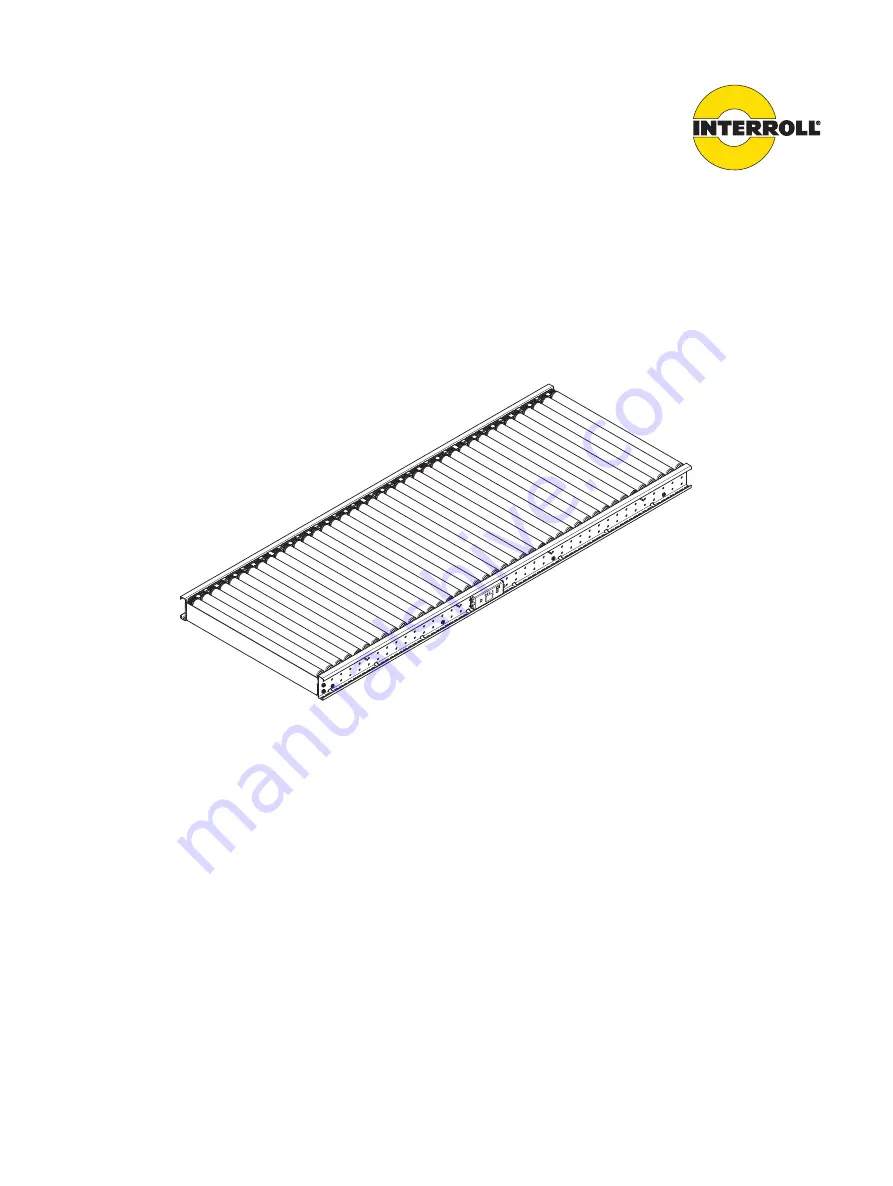
Interroll Roller conveyor – straight
SH 1110Rated width 405 mm (S), 710 mm (M), 862 mm (L)
Version 1.0 (06/2022) enTranslation of original operating instructions
Page 1: ...ED BY EFFICIENCY Installation and Operating Instructions Interroll Roller conveyor straight SH 1110 Rated width 405 mm S 710 mm M 862 mm L Version 1 0 06 2022 en Translation of original operating instructions ...
Page 2: ...ctual property right Texts images graphics and the like as well as their arrangement are protected by copyright and other protection laws Reproduction modification transfer or publication of any part or the entire content of the document in any form is prohibited This document is intended exclusively for information purposes and for intended use and does not authorize replicating the respective pr...
Page 3: ... Field of use 8 Changes to the module 8 Unintended use 9 Personnel qualification 9 Operators 9 Service personnel 9 Electricians 9 Personal protective equipment 10 Dangers 11 Safety devices 11 Heat 11 Electricity 11 Rotating parts 11 Parts lying around or falling off 11 Risk of injury due to faults during operation 11 Insufficient hygiene 11 Maintenance intervals 11 Interfaces to other devices 12 O...
Page 4: ...roller curve 30 Straight roller conveyor straight module belt conveyor 80 31 Straight module belt conveyor 50 straight roller conveyor 32 Straight roller conveyor lateral diverter 33 Straight roller conveyor front diverter 34 Initial startup and operation 35 Initial startup 35 Operation 36 Before every operation start 36 During operation 36 Procedure in case of accident or fault 36 Cleaning 37 Pre...
Page 5: ... reflector 50 Troubleshooting 51 In case of a fault 51 Troubleshooting 51 Spare and wear parts 53 Ordering information 53 Spare part designation 54 Spare parts list 55 Decommissioning and disposal 56 Environmental protection regulations 56 Declaration of incorporation 57 Declaration of incorporation 59 Appendix 61 Warranty for Interroll roller conveyors 61 Restrictions 61 Exceptions 61 Interroll S...
Page 6: ...n addition to these installation and operating instructions special contractual agreements and technical documents apply to special versions of the module and its additional equipment Installation and operating instructions are part of the module 4 To ensure trouble free and safe operation as well as the settlement of possible warranty claims always read these installation and operating instructio...
Page 7: ...isk that will result in death or serious injury if it is not avoided WARNING Identifies a danger with medium risk that could result in death or serious injury if it is not avoided CAUTION Identifies a danger with low risk that may result in minor or medium injury if it is not avoided NOTICE Identifies a danger that results in property damages Symbols This symbol marks useful and important informat...
Page 8: ...ea of use Intended use The module may only be used for industrial applications and in an industrial environment to convey roller conveyor ready goods such as all types of boxes packaged food or beverage units The module is an incomplete machine and must be integrated into a complete system prior to operation Field of use The module is dimensioned only for a certain field of use and may not be oper...
Page 9: ...he module is not intended for private end customers Use in a residential area is prohibited without additional assessment and without the use of EMC protective measures that have been adapted accordingly Personnel qualification Unqualified personnel cannot recognize risks and as a result is subject to greater dangers 4 Authorize only qualified personnel to perform the activities described in these...
Page 10: ...perating instructions Personal protective equipment 4 For all work such as assembly maintenance and cleaning tasks wear personal protective equipment that is suitable and appropriate for the hazard situation Close fitting work clothing Protective gloves Safety shoes Hard hat Hearing protection ...
Page 11: ...ntrol cabinet Main power switch to OFF Rotating parts 4 Never wear loose clothing 4 Never wear jewelery such as necklaces or bracelets 4 If you have long hair always wear a hair net Parts lying around or falling off 4 Remove equipment or material which is not required from the workspace 4 Wear safety shoes 4 Specify and monitor careful placement of the goods on the conveyor Risk of injury due to f...
Page 12: ...mplete system and operated as part of the system Special mode Special operation refers to all operating modes that are required to guarantee and maintain regular operation Special operating mode Explanation Comment Transport storage Loading and unloading transport and storage Assembly initial startup Installation at the end customer and performing the test run Cleaning External cleaning without re...
Page 13: ...d cartons or boxes Depending on the size of the module the rated width is 405 mm S 710 mm M or 862 mm L The module s rollers are driven by several PolyVee belts running from roller to roller The drive is provided by an Interroll RollerDrive EC5000 Using the Interroll RollerDrive allows for a compact design Since the drive is located within the side profiles the individual modules can be installed ...
Page 14: ...000 Max electrical power per zone 35 W Rated voltage 24 V Rated current 2 4 A Starting current 5 5 A Drive medium PolyVee belt Control variants MultiControl Bus Interface IPX5 housing Roller type IP55 roller Roller diameter 50 mm Roller material Stainless steel Max number of rollers per zone 14 rollers Distance of roller center to roller center pitch distance 60 mm Zone length ZL ZL number of roll...
Page 15: ...y includes Rack including side frames bracing Drive RollerDrive Rollers drive rollers carrying idlers Finger guards End plates Optional MultiControl Photo cell and reflector sensor holder and universal support Side guides side guide brackets and universal support Connector sets incl module connectors and contact guards Electronics Supports The side guide profiles and sensors are delivered installe...
Page 16: ...ypePlate Level Layout Position No Sales Order No Pos Serial Number Build Year Weight kg 10 4 1 3 2 5 7 8 9 6 Nameplate 1 Arrow in transport direction 6 Machine number 2 Company address 7 Serial number 3 Type designation 8 QR code 4 Level 9 Year of manufacture 5 Layout item no 10 Weight in kg The information on the nameplate is used to identify the conveyor The type designation is required to use t...
Page 17: ... Do not expose the module to strong temperature fluctuations since these could damage the electrical components Loosen the transport locks around the package The crossbeams above the top module can then be removed thereby exposing the module The individual module is lifted out of the package using a suitable lifting device After the delivery 4 Inspect module for transport damages 4 Immediately not...
Page 18: ...able photo cell and reflector are already pre assembled and connected The side guides universal support side guide brackets and side guide profiles are also delivered assembled The installation tasks are divided into two sections Setting up the module Integrating the module into a complete system To be observed during installation Electrical installation DANGER Danger energized cable ends 4 Electr...
Page 19: ...nding During installation of the module its grounding must be ensured A grounding connection which is fastened at the supports is intended for this purpose It is recommended to connect a grounding connection with grounding cable every 20 m Orientation 4 Align the module using the height adjustable feet of the support The roller top edge for roller conveyors or the module conveyor top edge for modu...
Page 20: ...g heavy loads 4 During the installation and replacement of conveyor modules or heavy spare parts always work in pairs or use suitable lifting devices Fasten screws with a tightening torque of 19 Nm The module sits on at least one support Each support has two height adjustable feet 4 4 Place the module on the supports 4 Position the supports underneath the module 4 Fasten the rack with screws 3 and...
Page 21: ...e assembled but integration into a complete system may still require individual installation tasks Install the universal support see Installing the universal support page 22 Fasten the side guide see Installing the side guide page 24 Install photo cell and reflector see Installing the photo cell and reflector page 25 Attach the module connectors and contact guards see Connecting the modules page 2...
Page 22: ...ned before startup depending on their use for the installation of adjustable side guide photo cell or reflector 1 5 4 2 6 3 7 1 Side frame 5 Clamping plate 2 Side guide bracket 6 Torx screw 3 Torx screw 7 Universal support 4 Mounting bracket Z bracket WARNING Risk of injury from crushing and electrocution Installation and maintenance tasks on a conveyor system while it is in operation can cause cr...
Page 23: ...pport but do not remove it 4 Bring clamping plate 5 with universal support 7 from below into position at the profile of the side frame The profile of the side frame is located between clamping plate and universal support 4 Tighten the screw 6 at the desired location 4 Push side guide bracket 2 onto the mounting bracket 4 of the universal support 7 Fasten screws with a tightening torque of 6 Nm 4 P...
Page 24: ...sks on a conveyor system while it is in operation can cause crushing and electric shock 4 Power down the entire conveyor module and ensure that it cannot be started accidentally Fasten screws with a tightening torque of 6 Nm Requirement R The module is shut down 4 Install the universal support see Installing the universal support page 22 4 Loosen screw 4 slightly The bottom part of side guide brac...
Page 25: ...nd electrocution Installation and maintenance tasks on a conveyor system while it is in operation can cause crushing and electric shock 4 Power down the entire conveyor module and ensure that it cannot be started accidentally Photo cell and reflector can be installed along the C profile of the side frame The flexible universal support enables adjusting the sensors with respect to height and distan...
Page 26: ...n 4 Loosen screw 3 in the universal support 5 but do not remove it 4 Bring clamping plate 6 with universal support 5 from below into position at the profile of the side frame 7 The profile of the side frame is located between clamping plate and universal support 4 Tighten the screw 3 at the desired location The fine adjustment of the photo cell is done with the vertical adjustment of the sensor ho...
Page 27: ...low into position at the profile of the side frame 4 The profile of the side frame is located between the clamping plate and universal support 4 Tighten the screw 6 at the desired location 4 After installing the photo cell and reflector Connect the photo cell to the control of the module with a cable 4 Check whether both LEDs are lit 4 If the yellow LED flashes position reflector and photo cell re...
Page 28: ...nding between modules If no profile connectors are used alternative measures must be taken for grounding The modules are aligned based on the top edge of the roller conveyor or module conveyor Suitable tools for alignment are a spirit level or rotation laser During setup of the conveyor system check for passageways for personnel Install crossings as necessary Fasten screws with a tightening torque...
Page 29: ...4 Position the modules to be connected 4 7 in such a way that the side profiles are aligned 4 Align the top edges of the module by using the height adjustable feet of the supports 4 Check horizontal alignment with a spirit level or rotation laser 4 Secure the adjusted height 4 Connect the side profiles of the modules form fit with each other on both sides by using a module connector 6 4 Fasten the...
Page 30: ...r 1 see Removing installing the end plate page 43 4 Position the modules to be connected 1 4 in such a way that the side profiles are aligned 4 Align the top edges of the module by using the height adjustable feet of the supports 4 Secure the adjusted height 4 Check alignment with a spirit level or rotation laser 4 Connect the side profiles of the modules 1 4 each with one module connector 6 form ...
Page 31: ...les are aligned or at a right angle to each other 4 Align the top edges of the module by using the height adjustable feet of the supports 4 Check horizontal alignment with a spirit level or rotation laser 4 Secure the adjusted height 4 Attach contact guard 4 at the bottom at side profile of module belt conveyor 6 and fasten it with screws 1 4 Attach contact guard 5 at the top at side profile of mo...
Page 32: ...nected 2 5 in such a way that the side profiles are aligned or at a right angle to each other 4 Align the top edges of the modules by using the height adjustable feet of the supports 4 Check alignment with a spirit level or rotation laser 4 Secure the adjusted height 4 Attach contact guard 4 at side profile of module belt conveyor 5 and fasten it with screws 1 4 Attach contact guard 3 at side prof...
Page 33: ...he side profiles are aligned 4 Align the top edges of the modules by using the height adjustable feet of the supports 4 Check horizontal alignment with a spirit level or rotation laser 4 Secure the adjusted height 4 Attach contact guard 4 at side profile of roller conveyor 6 and fasten it with screws 5 4 Fasten module connector 7 on the right and left at the bottom of the side profile of the diver...
Page 34: ...incline or decline 4 Position the modules to be connected 1 4 in such a way that the side profiles are aligned 4 Align the top edges of the modules by using the height adjustable feet of the supports 4 Check horizontal alignment with a spirit level or rotation laser 4 Secure the adjusted height 4 Attach contact guard 2 at side profile of roller conveyor 4 and fasten it with screws 3 4 Fasten the m...
Page 35: ...l startup and operation Initial startup WARNING Risk of injuries due to incorrect handling 4 Check electrical connections and protective devices 4 Remove the materials from the module 4 Remove unauthorized persons from the danger zone 4 Wear safety shoes and work clothing The module has been checked at the factory ...
Page 36: ...not remove the protective covers 4 Wear personal protective equipment 4 Avoid jewelry and bracelets CAUTION Risk of shearing between product and rollers or product and universal support of the side guide 4 Do not reach inside from below or from the side 4 Take additional protective measures e g secure the gap of rollers at workplaces using fillers or covers with a gap of maximum 5 mm 4 If material...
Page 37: ...lipping on the floor Slipping on a wet floor can lead to a fall The fall can cause injuries 4 Immediately pick up leaking and spilled fluids using suitable means The conveyor platform is generally designed for protection rate IP55 IP identifier Definition 5 dust protection Dust is not completely prevented from entering but dust may not enter at a magnitude that would impair the function of the mod...
Page 38: ...eals during cleaning 4 Observe a maximum water pressure of 8 bar 116 psi 4 Move the nozzle continuously and evenly over the entire module 4 Ensure that the distance between the nozzle of the water hose and the conveyor is at least 100 cm NOTICE Risk of damage to the conveyor due to improper cleaning 4 Never use an acidic cleaner together with a chlorinated cleaner since the resulting dangerous chl...
Page 39: ...1 0 06 2022 en Translation of original operating instructions 39 4 Spray off with water 8 bar 35 C 4 After cleaning check surfaces grooves and other recesses for residues 4 Wipe the floor dry 4 Observe the corresponding certificates at www interroll com ...
Page 40: ...pylene PP and polyamide PA Acidic acid aqueous solution 5 Calcium chloride aqueous solution 10 Dimethylformamide Dioctylphthalate Ethyl ether Isopropanol Soap solution aqueous solution Sodium carbonate aqueous solution 10 Sodium chloride aqueous solution 10 Sodium nitrate aqueous solution 10 Sodium thiosulphate aqueous solution 10 Water cold The resistance of the polymers is affected by temperatur...
Page 41: ...k in pairs 4 Use suitable loading and lifting equipment Secure the module against falling or tipping CAUTION Risk of injury due to improper handling or accidental motor starts 4 Maintenance work and cleaning must only be performed by qualified and authorized persons 4 Perform maintenance work only after switching off the power Ensure that the conveyor cannot be switched on accidentally 4 Set up si...
Page 42: ...de guides Readjust as necessary RollerDrive EC5000 1 month after installation of module Check for firm seating in the side profile Retighten as required Monthly Check temperature Replace as required Monthly Check for noise Replace as required Monthly Check for damage Replace as required Monthly Check for true running Replace as required Monthly Check electrical connections Replace as required Poly...
Page 43: ...t be started accidentally Fasten screws with a tightening torque of 19 Nm Removing installing the end plate 1 1 2 End plate 1 Torx screw 2 End plate The installation of the end plate is required at the end of the conveyor section and for connections with other module belt conveyors The removal of the end plate is required at connections with other roller conveyors or roller curves Requirement R Th...
Page 44: ...e tasks on a conveyor system while it is in operation can cause crushing and electric shock 4 Power down the entire conveyor module and ensure that it cannot be started accidentally Fasten screws with a tightening torque of 19 Nm Requirement R The module is shut down 4 Remove finger guard and PolyVee belt see Replacing the finger guard and PolyVee belt page 48 4 Unscrew taper screws 1 in roller 2 ...
Page 45: ...2 1 Torx screw 2 Conveyor bracing WARNING Risk of injury from crushing and electrocution Installation and maintenance tasks on a conveyor system while it is in operation can cause crushing and electric shock 4 Power down the entire conveyor module and ensure that it cannot be started accidentally Fasten screws with a tightening torque of 19 Nm Requirement R The module is shut down 4 Unscrew screws...
Page 46: ...veyor module and ensure that it cannot be started accidentally Fasten screws with a tightening torque of 19 Nm Requirement R The module is shut down 4 Disconnect the motor connecting cable from the control system or from the extension cable 4 Remove finger guard and PolyVee belt see Replacing the finger guard and PolyVee belt page 48 4 Loosen the nut on the cable side of the RollerDrive 4 Loosen t...
Page 47: ...ing MultiControl 1 Disassembling MultiControl 1 MultiControl Requirement R The module is shut down 4 Detach cable from the MultiControl 4 Loosen screws with which the MultiControl 1 is attached to the side frame and pull off MultiControl 4 Properly dispose of the old MultiControl 4 Fasten new MultiControl 1 with screws at the side frame ...
Page 48: ...intenance tasks on a conveyor system while it is in operation can cause crushing and electric shock 4 Power down the entire conveyor module and ensure that it cannot be started accidentally Requirement R The module is shut down 4 To do so unscrew the screw 2 remove the top part 3 and pull the bottom part 4 out from below 4 Properly dispose of the old finger guard 4 Loosen taper screw in roller and...
Page 49: ... system while it is in operation can cause crushing and electric shock 4 Power down the entire conveyor module and ensure that it cannot be started accidentally Replacing the photo cell 4 3 1 2 Photo cell 1 Photo cell 3 Sensor holder 2 Photo cell housing 4 Fastening clip The photo cell is replaced together with the photo cell housing and the fastening clip The fine adjustment of the photo cell is ...
Page 50: ...ED green LED yellow Meaning On Off Photo cell is operational No signal from reflector On On Photo cell is correctly adjusted Light beam is well reflected On Flashing Photo cell is operational Weak signal Reflector is dirty damaged or not correctly adjusted Replacing the reflector 2 1 3 Reflector 1 Reflector 3 Fastening clip 2 Sensor holder The reflector is replaced in the same way as the photo cel...
Page 51: ...jam between the side guides Conveying goods sit on the module at an angle Align conveying goods parallel to the side guide Center of gravity of the load is not centered Align the center of gravity of the load Transport process cannot be started and RollerDrive does not run Main switch and or control system turned off is the LED on the MultiControl lit Check the switch positions if necessary turn o...
Page 52: ...xcessive current consumption Short circuit Check electrical connections and replace defective parts Transport weight too high Observe maximum weight Noise development squeaking whistling Roller bearing defective Replace the rollers see Replacing the roller page 44 Motor or gear box damaged Analyze error according to RollerDrive EC5000 Operating Instructions Replace motor if necessary ...
Page 53: ...e parts for the connector sets can be ordered from Interroll upon request The different connector sets are matched to all available conveyor modules and include static connectors as well as safety relevant protective devices Ordering information Ordering spare and wear parts requires the exact identification of the module see type plate The following information is required for an order Machine nu...
Page 54: ...erroll Roller Conveyor SH 1110 Spare and wear parts 54 Version 1 0 06 2022 en Translation of original operating instructions Spare part designation 4 8 3 2 6 7 5 1 12 14 13 11 9 10 Roller Conveyor SH 1110 ...
Page 55: ...071 S 3 Roller IP55 ø50 S M L See project data S 4 Side guide 1129435 S 5 Self threading screw for finger guard 1129142 6 Finger guard top part bottom part 64101223 S 7 Side guide bracket 63172677 S 8 Drive roller RollerDrive EC5000 PolyVee EL 405 S EL 710 M EL862 L See project data S 9 Bracing 63170542 S 63170541 M 63170540 L S 10 Mounting bracket Z 63172672 S 11 Taper screw for roller and drive ...
Page 56: ...lations For all work on and with the module the legal regulations concerning waste avoidance and proper disposal and recycling must be followed NOTICE Substances with a water hazard class such as greases and oils hydraulic oils coolants or cleaning agents with solvents may not be allowed to come into contact with the ground or reach the sewer system 4 Store transport catch and dispose these substa...
Page 57: ...1 5 2 1 5 4 1 5 5 1 5 6 1 5 8 1 5 9 1 6 1 1 6 2 1 6 4 1 7 1 1 7 2 1 7 3 1 7 4 The special technical documents mentioned in Appendix VII B have been prepared and will be transmitted to the responsible authority if necessary Transmission is performed electronically Applicable EC Directives Machinery Directive 2006 42 EC EMC Directive 2014 30 EU Applicable EC EU regulations Regulation 10 2011 EU Regu...
Page 58: ...erroll Roller Conveyor SH 1110 Declaration of incorporation 58 Version 1 0 06 2022 en Translation of original operating instructions Hueckelhoven Baal dated 16 May 2022 Dr Hauke Tiedemann Managing Director ...
Page 59: ... 1 5 6 1 5 8 1 5 9 1 6 1 1 6 2 1 6 4 1 7 1 1 7 2 1 7 3 1 7 4 The specific technical documentation according to Annex VII B has been prepared and will be submitted to the competent authority if required The commissioning of the incomplete machine is prohibited until the conformity of the overall machine system in which it is installed with the UK Supply of Machinery Safety Regulations 2008 has been...
Page 60: ...t into operation when it has been established that the complete machine system in which the partly completed machine is to be installed is to be installed complies with the provisions of this directive Authorised for compiling technical documentation Interroll Trommelmotoren GmbH Opelstr 3 Germany 41836 Hueckelhoven Hueckelhoven 16th May 2022 Dr Hauke Tiedemann Managing Director ...
Page 61: ...ce notes from Interroll Operation of the motor without suitable motor protection Not connecting the internal Interroll thermal circuit breaker if available Reversing the rotational direction before the motor has reached complete standstill Use of the roller conveyor outside the specifications stated on the nameplate and or in the current Interroll catalog or quotation Repairs modifications or conv...
Page 62: ...Interroll Roller Conveyor SH 1110 62 Version 1 0 06 2022 en Translation of original operating instructions ...
Page 63: ...Interroll Roller Conveyor SH 1110 Version 1 0 06 2022 en Translation of original operating instructions 63 ...
Page 64: ...For your local contacts please visit interroll com contact copyright Version 1 0 06 2022 en Translation of original operating instructions ...