background image

DCS 300 User’s Manual

4-4

Connecting the DCS 300 to the 900 MHz RF Network

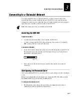
The DCS 300 can communicate with Intermec’s 900 MHz RF network. To
communicate with this network, the DCS 300 contains a 900 MHz RF card that
connects by an RS-485 cable to 9181 Base Radio Units (BRUs). This RF card supports
up to four ports. Devices can roam between these BRUs.

Note: 

The 900 MHz card is not available on the 0300D. The 0300D can only connect to

a network through serial or Ethernet connections.

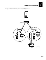
The BRUs transmit information from the DCS 300 to Intermec 900 MHz RF devices
and receive signals from them. The illustration on the next page shows an example of a
DCS 300 connected to the Intermec 900 MHz RF network.

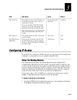
To connect the DCS 300 and the BRU, Intermec provides you with a 4-port interface
cable. Insert one end of the cable into the port on the RF card. Use the Intermec cable
kit (Part No. 055003) or equivalent to connect to one of the DNLN ports on the other
end of the cable. You also need a Belden 89688 cable (Part No. 583326) or equivalent.

Note: 

If you are using the 9180 Network Controller to communicate with the 9181

BRU, you need to configure these BRUs using the 9180 controller’s configuration
menu. Refer to your 9180 user’s manual.

Summary of Contents for DCS 300

Page 1: ...P N 067296 005 User s Manual DCS300 ...

Page 2: ...used for any other purpose without written permission of Intermec Information and specifications in this manual are subject to change without notice 2001 by Intermec Technologies Corporation All Rights Reserved The word Intermec the Intermec logo INCA under license MobileLAN JANUS IRL Trakker Antares EZBuilder TE 2000 Data Collection Browser dcBrowser Universal Access Point UAP Duratherm EasyCoder...

Page 3: ...oughout the entire manual 003 3 99 Added addendum 069283 001 that documents the v1 2 software Includes information on using WTP devices that communicate in Norand Native mode Also documents using TN3270 TN5250 terminal sessions 004 9 99 Modified addendum to document v1 3 software Includes information on the Data Collection Browser dcBrowser Removed Fast Setup Quick Reference Guide 005 10 01 Incorp...

Page 4: ...DCS 300 User s Manual blank ...

Page 5: ...erstanding the Rear Panel 1 7 Plugging In the Power Cord 1 8 Connecting an Uninterruptable Power Supply 1 9 Plugging In the Keyboard 1 11 Connecting the Monitor 1 12 Connecting a Modem 1 13 Mounting the DCS 300 in a Rack 1 15 Turning the DCS 300 On and Off 1 16 Turning On the DCS 300 1 17 Turning Off the DCS 300 1 18 Learning About the DCS 300 Chapter Checklist 2 3 About the DCS 300 Local Interfac...

Page 6: ...ime Configuration 2 19 Restoring Your User Files 2 20 Deleting User Files 2 22 Starting and Stopping the Downline Network 2 23 Starting Data Collection 2 23 Stopping Data Collection 2 24 Accessing a Command Prompt 2 25 Connecting to the Upline Network Chapter Checklist 3 3 Connecting to an Ethernet Network 3 4 Installing the DCS 300 3 4 Configuring the Ethernet Card for TCP IP 3 5 Using DNS 3 7 Cl...

Page 7: ...Configuration 3 25 Connecting to the Intermec RF Network Chapter Checklist 4 3 Connecting the DCS 300 to the 900 MHz RF Network 4 4 Configuring the RF Card 4 6 Adding an RF Card 4 8 Setting the Time Parameters 4 10 Defining Default Hosts 4 12 Defining the RF Card Devices 4 13 Enabling the RF Card Devices 4 14 Editing an RF Card Device 4 15 Connecting the DCS 300 to the UDP Plus Network 4 17 Config...

Page 8: ...bout the Controller Parameters 5 6 Adding a 9154 Controller 5 6 Adding a 9161 Controller 5 9 Adding a 9180 v1 x Controller 5 11 Adding a 9180 v2 0 Controller 5 13 Setting the Time Parameters 5 15 Defining Default Hosts 9180 v2 0 5 18 Defining the 9180 v2 0 Devices 5 19 Identifying the CrossBar Devices 5 20 Editing a CrossBar Device 5 22 Saving Your Runtime Configuration 5 23 Running Data Collectio...

Page 9: ...NA Local Node 7 15 Selecting an IBM Mode 7 16 Setting and Removing the User ID and Password 7 16 Performing a Double Pass Through on an IBM AS 400 Host 7 17 Configuring 3270 SNA TE 7 18 Configuring the Hosts 7 18 Configuring the DCS 300 7 18 Adding an IBM SNA Host 7 20 Filling the NAU Pool 7 22 Configuring Native Applications 7 23 Editing the Host Application 7 23 Converting to the DCS 300 From th...

Page 10: ...8 5 Setting Up Peer to Peer Links 8 6 Using International Text Pass Through 8 8 Adding a Transaction 8 9 Adding a Transaction Field 8 10 Saving and Activating Your Runtime Configuration 8 11 Communicating With TCP IP Applications 8 11 How the DCS 300 Communicates With Applications 8 13 Understanding Transaction Routing in a TCP IP Network 8 14 Communicating Through the Direct TCP IP Socket Interfa...

Page 11: ...uring the SNA Local Node 9 16 Adding a 3270 SNA Terminal Session 9 17 Adding an IBM SNA Host 9 18 Configuring the SNA Local Node 9 20 Saving and Activating Your Runtime Configuration 9 21 Starting a Host Session 9 21 Mapping Terminal Keyboards to the DCS 300 Keyboard 9 22 Running Screen Mapping Chapter Checklist 10 3 About Screen Mapping 10 5 About Script Files 10 7 Preparing to Use the Script Bui...

Page 12: ...Script 10 31 Selecting Host Screens for the Current Transaction 10 32 Defining Next Screen Sequences for Host Screens 10 33 Selecting Host Screen Fields for the Current Host Screen 10 35 Adding a Host Screen Field 10 36 Getting Host Screen Field Attributes From a Host Screen 10 38 Selecting Regions for the Current Host Screen 10 39 Adding a Region 10 40 Getting a Region From a Host Screen 10 43 Ca...

Page 13: ...11 5 Troubleshooting Tools 11 7 Viewing the Configuration 11 8 Viewing Error Messages 11 9 Message Box Error Messages 11 10 Error Log Error Messages 11 10 Viewing the Hot Standby Files 11 13 Using Remote Console 11 15 Configuring the NetOp Host DCS 300 11 15 Configuring Security 11 18 Configuring the NetOp Guest Remote PC 11 20 Using the Trace Utilities 11 22 Configuring the DCS 300 Trace Utility ...

Page 14: ...e Download Server A 12 Copying Information Between Terminals or Groups A 13 Using the Download Server to Transfer Files A 14 Using Download Server Commands to Transfer Files A 15 Using the DCS 300 to Configure Trakker Antares Terminals A 17 Upgrading the DCS 300 and Devices Upgrading the DCS 300 Software B 3 Upgrading to Screen Mapping B 5 Using the DCS 300 to Upgrade Trakker Antares Terminals B 6...

Page 15: ...Transactions C 13 How the DCS 300 Ensures Data Integrity C 13 Interactivity With Devices C 13 Fully Interactive System C 14 Partially Interactive System C 14 Noninteractive System C 14 Data Integrity Modes C 15 Faster Mode C 15 Safer Mode C 15 Retaining Transactions in Memory C 16 How the DCS 300 Sets Application Status C 17 Active Applications C 17 Nonactive Applications C 18 Sending Hot Standby ...

Page 16: ...DCS 300 User s Manual ...

Page 17: ... and equipment and data can be damaged if you do not follow the safety warnings and cautions Do not repair or adjust alone Do not repair or adjust energized equipment alone under any circumstances Someone capable of providing first aid must always be present for your safety First aid Always obtain first aid or medical attention immediately after an injury Never neglect an injury no matter how slig...

Page 18: ...ccurrence de mort ou de blessures graves aux personnes manupulant l équipement Caution A caution alerts you to an operating procedure practice condition or statement that must be strictly observed to prevent equipment damage or destruction or corruption or loss of data Conseil Une précaution vous avertit d une procédure de fonctionnement d une méthode d un état ou d un rapport qui doit être strict...

Page 19: ...icate using UDP Plus WTP devices refers to all the devices and terminals that communicate using WTP wireless transport protocol Data collection devices and devices refers to the JANUS devices Trakker Antares terminals WTP devices and other devices that communicate through the DCS 300 Conventions This manual uses these conventions to explain how to use your mouse and to emphasize input from a PC ke...

Page 20: ...a command The bar code labels in this manual are printed in the Code 39 symbology Each bar code includes the name and human readable interpretation 0300U 001 The asterisks at the beginning and end of the human readable interpretation are the start and stop codes for a Code 39 bar code label If you are creating bar code labels with a bar code utility it may automatically supply the asterisks as the...

Page 21: ...box Deleting an Object 1 In the dialog box from the list box select an object to delete 2 Choose Delete A message box appears confirming that you want to delete the object Note You may not be able to delete an object if it is linked to another object 3 Choose Delete The object is removed from the list box 4 Choose OK to save your changes and return to the main menu Other Intermec Manuals You may n...

Page 22: ...DCS 300 User s Manual ...

Page 23: ...Getting Started 1 ...

Page 24: ...DCS 300 System Manual blank ...

Page 25: ... Y Unpack the DCS 300 1 5 Y Identify the components on the front and rear panels 1 6 Y Plug in the power cord 1 8 Y Connect the uninterruptable power supply 1 9 Y Plug in the keyboard 1 11 Y Connect the monitor 1 12 Y Optional Connect the modem 1 13 Y Optional Mount the DCS 300 in a rack 1 15 Y Learn how to turn on and turn off the DCS 300 1 16 If you already understand and have performed these ta...

Page 26: ...cations for TCP IP and APPC Direct TCP IP socket interface between hosts and devices Optional Script Builder Tool Part No 067190 that lets you create custom screens and script files so that you can run VT ANSI SNA5250 TN5250 SNA3270 or TN3270 screen mapping Optional RF card that supports Intermec s 900 MHz RF network This card supports up to four 9181 Base Radio Units BRUs The RF card is not avail...

Page 27: ...tact your local Intermec representative DCS 300 AC power cord Keyboard 3 5 inch disk to use for backing up your system files and runtime configuration Two rack handles and four flat head screws Two rack ears and four round head screws Important DCS 300 Information DCS 300 Quick Start Guide 4 Report any damage or defects Intermec thoroughly tested and inspected the DCS 300 before it was shipped to ...

Page 28: ...hows the front panel with the security panel up lock showing and with the security panel down On Off button showing 0301U009 eps FAN On Off button CD ROM drive Lock Reset button Power LED Activate LED Disk drive Security panel Security panel Component Description Power LED Indicates that the DCS 300 has power Activate LED Indicates that the DCS 300 is on and is communicating Security panel and loc...

Page 29: ...uating your DCS 300 do not place it where the fan is obstructed LPT1 Provides parallel port connection for accessories Video port Connects the monitor to your DCS 300 Ethernet port Provides a 10 100 Mbps Ethernet connection AC in Connects to one end of the AC power cord that provides power to the DCS 300 COM1 COM2 Provides serial port connections for external Intermec controllers a modem or other ...

Page 30: ...you use a UPS in locations that have wide variations in AC power For help see Connecting an Uninterruptable Power Supply later in this chapter Equipment Power cord 110V U S cord standard Or Power cord 220 250 VAC for UK Part No 586266 Power cord 220 250 VAC for Europe Part No 586267 Surge protector To connect the power cord 1 Locate the AC in port on the rear panel of the DCS 300 2 Insert the powe...

Page 31: ... error message is logged the UPS cuts off power to the DCS 300 You can configure the DCS 300 to automatically restart data collection when power returns For help see Setting the System Parameters in Chapter 2 Equipment Uninterruptable power supply North America Part No 589082 Uninterruptable power supply International Part No 589079 9F 9M cable for auto restoration Part No 589157 To connect a UPS ...

Page 32: ...ies dialog box appears 10 Choose UPS 11 In the Available Ports list box select the serial port on the DCS 300 that you used to connect to the UPS 12 Choose OK to save your changes 13 Click Close 14 Click Save and Activate and follow the instructions that appear The DCS 300 reboots Uninterruptable power supply To AC power 300U007 eps ...

Page 33: ...onnected to the DCS 300 whenever you boot it Equipment Keyboard standard To plug in the keyboard 1 Locate the keyboard port on the rear panel of the DCS 300 2 Insert the keyboard adapter into the keyboard connector 3 Insert the keyboard adapter into the keyboard port 4 Insert the mouse connector into a COM port 300U004 eps ...

Page 34: ...s Connecting the Monitor Equipment Monitor with cable and power cord not provided To connect the monitor 1 Locate the video port on the rear panel of the DCS 300 2 Insert the monitor cable into the video port 3 Insert one end of the power cord into the monitor and the other end into an AC power outlet ...

Page 35: ... console feature you may want to use a modem to let you access the DCS 300 using a PC with a modem Note You can also use the remote console support feature through a LAN or a WAN connection Equipment Modem 56 Kbps external with telephone cable and power cord for North America Part No 590887 International customers should use the U S Robotics Sportster modem 56 Kbps external ...

Page 36: ...of the serial cable into the serial port on the modem 5 Insert the other end of the serial cable into a COM port on the DCS 300 6 Press the power button on the DCS 300 The power LED turns on The main screen appears 7 From the main screen sidebar buttons choose System Maintenance The System Maintenance dialog box appears 8 In the System Maintenance list box select Install Accessories and then choos...

Page 37: ...nts found at the front or the rear of the server If you reduce the amount of free air to these ventilation openings you may affect the server operation Do not mount the server in any way that may make the rack unstable because of uneven mechanical loading Make sure that you consider the combined electrical loads on the supply circuit of all the equipment that is installed in the rack including the...

Page 38: ...d head screws Round head screw 2 places Flat head screw 2 places Security panel Security panel plate Rack handle Rack ear 300U025 eps Turning the DCS 300 On and Off Caution Always choose Shutdown DCS 300 before rebooting or turning off the server If you do not shut down the server properly you may lose data or damage files on the server Conseil Vous devez toujours arrêter le DCS 300 avant de le ré...

Page 39: ... box lists the network adapter cards in your DCS 300 Choose one of the following If you want this dialog box to appear every time the DCS 300 boots choose Show at Boot Time This dialog box may be helpful when troubleshooting the DCS 300 If you never want this dialog box to appear choose Hide at Boot Time The DCS 300 window appears ...

Page 40: ...sure that no system files or data are lost This process may take several minutes If you are using the DCS 300 local interface and you want to reboot the DCS 300 to activate your changes from the Shutdown DCS 300 message box choose Restart Note If you are using Remote Console you must choose the Restart button You cannot choose Shutdown and then press Ctrl Alt Del If you are using the Web browser i...

Page 41: ... activating them only Activate appears in the title bar this check box is grayed The DCS 300 will automatically activate your changes before it shuts down 3 Choose Shutdown to shut down the DCS 300 The DCS 300 needs to perform a series of shutdown activities which may take several minutes A message box appears letting you know when you can safely turn off the DCS 300 Or choose Restart if you want ...

Page 42: ...blank ...

Page 43: ...Learning About the DCS 300 2 ...

Page 44: ...DCS 300 User s Manual blank ...

Page 45: ... about the Web browser interface and how to navigate through it 2 9 Y Set the date and time 2 12 Y Set the system parameters 2 14 Y Understand the configuration files and how to restore the default configuration 2 16 Y Understand how to back up and restore the system and user files on your DCS 300 2 17 Y Understand how to start and stop the downline data collection network 2 23 Y Know how to acces...

Page 46: ... this interface to configure the upline network configure the data collection environment configure the host communications environment configure the host environment parameters manage the data collection network set system parameters perform system maintenance run diagnostics perform system reporting manage system runtime and user files upgrade your DCS 300 software and licenses upgrade your Trak...

Page 47: ... you that you have made changes to the configuration that have not been saved or activated When you choose Save Configuration or Save and Activate these prompts disappear Toolbar buttons The buttons on the screen define the host environment to which you are connecting the DCS 300 Sidebar buttons The buttons on the right side of the screen perform system functions on the DCS 300 such as backing up ...

Page 48: ...ur Help window to see more of a topic at one time or to see more of the configuration window Once the Help window appears you operate the Help system by selecting topics by choosing commands from the Help menus or by choosing the Help control buttons at the bottom of the Help window Topics that you can jump to are shown in colored or underlined text To jump to another help topic Double click the t...

Page 49: ...from field to field Press Ctrl or Alt and then the letter underlined in the field or button name Activate the buttons in a dialog box Use the mouse to click them Press Ctrl or Alt and the letter underlined in the button name If any button is highlighted choose another button by pressing the letter underlined in the button name without pressing Ctrl or Alt Go to the end of a file Go to the top of a...

Page 50: ...log box Help Choose Help in any dialog box to obtain help on the fields in that dialog box Close Choose Close to exit a dialog box Add Choose Add to add a new item such as a host A dialog box appears Enter the values into the fields Choose OK to add the item Choose Cancel to remove the item Edit Select the item you want to change and choose Edit A dialog box appears Edit the values in the fields C...

Page 51: ...h as its name and its software version Note If you have a DNS server you can enter the logical name for the DCS 300 instead of the IP address to access the home page The DCS 300 home page has these parts Web browser menu This menu at the top of the window helps you configure operate and navigate the Web browser For help select Help from the Web browser menu Web browser buttons These buttons at the...

Page 52: ...ork To open the DCS 300 home page Note If you access the Internet by using a proxy server you must add the IP address of the DCS 300 to your Exceptions list The Exceptions list contains the addresses that you do not want to use with a proxy server 1 Start a Web browser on your PC 2 In the Address line or the Go to line enter http and the IP address of the DCS 300 and then press Enter For example h...

Page 53: ...ge appears To the left of the Welcome page are the Contents Index and Search tabs Use the Contents tab to display the books that are available Double click the books to display pages that contain procedures To get help on configuring the DCS 300 1 From the navigation menu click Configuration 2 If a security screen appears type INTERMEC in the User Name field and in the Password field and click OK ...

Page 54: ...k which is the date and time that is set on your PC Note When you choose the Change Now button you immediately change the date and time on the DCS 300 To set the date and time 1 Open the DCS 300 home page For help see About the Web Browser Interface earlier in this chapter 2 Click Configuration If a security screen appears type INTERMEC in the User Name field and in the Password field and click OK...

Page 55: ...pand the System menu and click Date and Time The Change Date and Time page appears 4 Enter the date in the date field or click the Popup Calendar to select a date 5 Enter the time in the time field 6 Click Change Now The date and time are now set to what you selected ...

Page 56: ... System Parameters When you set system parameters you are defining the operating parameters for the DCS 300 To set the system parameters From the main screen sidebar buttons choose System Parameters The System Parameters dialog box appears ...

Page 57: ...tion ID from the transaction fields Predefined comma Bad ID response Optional The message that the DCS 300 sends to the source of the transaction if the DCS 300 does not recognize the transaction ID Use this field if you want to make sure that there is always a response for a failed delivery of a transaction 1 to 40 alphanumeric and special characters None Maximum connections Peer to peer A tuning...

Page 58: ... data collection the active configuration file is the file that the DCS 300 uses Restoring the Default Configuration You can use the DCS 300 local interface to restore the current default configuration This procedure stops data collection discards any unsaved and unactivated changes and reboots the DCS 300 If you have used the Install Accessories dialog box to connect a modem or UPS or if you have...

Page 59: ...floppy disk When you opened the DCS 300 package you unpacked a blank formatted 3 5 inch disk Use this disk to back up your system files and runtime configuration If your DCS 300 loses its configuration you can use these files to restore the DCS 300 You can also use the Web browser interface to back up your system files and runtime configuration These backed up files are stored with the current dat...

Page 60: ...ay want to back up your script SCR files You may also want to back up the NGERROR LOG file which contains error messages Note When backing up your user files you must use a separate 3 5 inch disk from the one you used to back up your runtime configuration To back up your user files 1 From the main screen sidebar buttons choose File Handling The File Handling dialog box appears 2 In the File Handli...

Page 61: ...rface to back up the system files and runtime configuration you stored these files on the DCS 300 hard drive The DCS 300 also periodically performs automatic backups of the configuration You can use the Web browser interface to restore either a manual backup or an automatic backup To restore the configuration using the DCS 300 local interface 1 From the main screen sidebar buttons choose System Ma...

Page 62: ...iguration page appears 4 Choose Last User Initiated Backup or choose Last Automatic Backup 5 Choose Begin Restore A message box appears informing you when the restore is completed 6 Choose OK Restoring Your User Files You can also use this feature to transfer files such as validation files or applications from a floppy disk to the DCS 300 To restore your user files 1 Insert the 3 5 inch disk that ...

Page 63: ...ox 5 In the Available Files list box add all the files that you want to restore to the Selected Files list box a Select the file name b Choose Select The file name appears in the Selected Files list box 6 In the Selected Files list box remove any of the files that you do not want to restore a Select the file name b Choose Remove The file name is removed from the Selected Files list box 7 Choose Re...

Page 64: ...d all the files that you want to delete to the Selected Files list box a Select the file name b Choose Select The file name appears in the Selected Files list box 4 In the Selected Files list box remove any of the files that you do not want to delete a Select the file name b Choose Remove The file name is removed from the Selected Files list box 5 Choose Delete Files A message box appears confirmi...

Page 65: ...box appears confirming that you want to save your changes and activate the configuration 2 Choose Activate A message box may appear informing you that the DCS 300 needs to reboot and that you need to choose OK Or a message box may appear informing you that your activate is successful 3 From the main screen sidebar buttons choose Start Data Collection The Start Data Collection message box appears 4...

Page 66: ...lection all data collection activities are stopped but any external Intermec controllers continue polling and buffering data Devices using programs that require a response directly from a destination interactive mode also stop until the DCS 300 is started again The Web browser interface uses the term downline network instead of data collection To stop data collection using the DCS 300 local interf...

Page 67: ... appears and then a message box appears informing you that data collection has been stopped Accessing a Command Prompt While maintaining or configuring the DCS 300 you may find your task is easier by accessing a command prompt You can get to a command prompt from either the DCS 300 local interface or using telnet To access a command prompt using the local interface 1 From the main screen sidebar b...

Page 68: ...blank ...

Page 69: ...Connecting to the Upline Network 3 ...

Page 70: ...DCS 300 System Manual 3 2 blank ...

Page 71: ...17 Y Install and configure the DCS 300 in the SDLC network 3 18 Y Understand how to use and configure the IP routes 3 21 Y Understand how to use and configure the auto fallback feature 3 23 Y Save your runtime configuration 3 25 Note DCS 300 v1 3 and later does not support a connection to the coaxial network If you already understand and have performed these tasks either connect the DCS 300 to ano...

Page 72: ...s Installing the DCS 300 The DCS 300 has a built in Ethernet interface Equipment needed An Ethernet cable that meets the requirements of your Ethernet network such as an Ethernet CAT5 cable Note The default configuration for the Ethernet interface is 10BaseT or 100BaseTX To install the DCS 300 1 Locate the Ethernet port 300U022 eps Ethernet port 2 Insert one end of the cable into the Ethernet port...

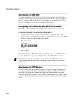
Page 73: ...can perform pseudo load balancing on your UDP Plus network For help see Using the Auto Fallback Feature later in this chapter Enter the TCP IP information manually From your network administrator obtain a valid IP v4 address for each Ethernet card You may also need to know the DCS 300 local host name and the subnet mask Enter this information in the TCP IP Protocol Configuration dialog box If you ...

Page 74: ...CP IP Protocol Configuration dialog box appears Field Description Value Default TCP IP card The Ethernet adapter that you are configuring Ethernet 1 Token Ring 1 Ethernet 1 Use DHCP This check box enables this network adapter card to be administered by a DHCP server Check Clear Clear Local host name Optional A meaningful name that identifies the DCS 300 host to the network 1 to 12 alphanumeric cha...

Page 75: ...DNS server you do not need to configure the DCS 300 with the IP addresses for the TCP IP hosts You only need to enter the host names However if you manually enter an IP address this address takes precedence over an address supplied by the DNS server In a DHCP environment the IP address changes frequently The host may obtain a new IP address every time it is restarted and reconnects to the network ...

Page 76: ...ot respond then the DCS 300 uses the next IP address However if the DNS server responds even if the response is a not resolved response the search stops x x x x where x is a value between 0 and 255 None Domain Names List of domains that are searched when an abbreviated IP name is entered You can enter up to six domain names If the host or device name is not found in the domain the DCS 300 searches...

Page 77: ...t Card for IEEE 802 2 After you install the DCS 300 you need to turn it on and configure its network adapter cards Ethernet supports both TCP IP and IEEE 802 2 protocols To configure the card for IEEE 802 2 you need to know the network adapter address Ethernet driver support and the maximum number of link stations This protocol is used for IBM connectivity It coexists with TCP IP in the network ad...

Page 78: ...format hex that identifies the card 020000000000 through FEFFFFFFFFFF The MAC address that is on the card Ethernet driver support The Ethernet frame type you are using IEEE 802 3 or Ethernet DIX Ethernet II IEEE 802 3 Maximum link stations The maximum number of link stations that can exist for all SAPs concurrently Or choose the Auto Calc button if you want the DCS 300 to determine the optimal val...

Page 79: ...e DCS 300 Equipment needed A token ring connection where you can connect the DCS 300 A cable to connect the DCS 300 to the connection Your token ring card comes with an RJ 45 to STP cable To install the DCS 300 1 Locate the slot that contains the token ring card The card connectors look like the figure below 0300U022 eps 2 Insert one end of the cable into the token ring port on the card and the ot...

Page 80: ...or the token ring card You may also need to know the DCS 300 s local host name and the subnet mask Enter this information in the TCP IP Protocol Configuration dialog box If you have two or more cards communicating using TCP IP each card must be on a different subnet DNS button Click this button to configure Domain Name System servers You can use Domain Name System servers to translate names of hos...

Page 81: ...to be administered by a DHCP server Check Clear Clear Local host name Optional A meaningful name that identifies the DCS 300 host to the network 1 to 12 alphanumeric characters ACCNET Local IP address A unique IP address that identifies the card in the DCS 300 host to the network This IP address must be a valid IP v4 address y x x x where y is a value between 1 and 223 not including 127 and x is a...

Page 82: ...es However if you manually enter an IP address this address takes precedence over an address supplied by the DNS server In a DHCP environment the IP address changes frequently The host may obtain a new IP address every time it is restarted and reconnects to the network DNS servers let the DCS 300 locate and connect to TCP IP hosts that are administered by a DHCP server The DCS 300 locates the host...

Page 83: ...plete domain name before attempting to use the DNS server to resolve the IP address Note If the host or device name has any dotted notation such as intermec com this list is not used 256 alphanumeric characters dash None Configuring the Token Ring Card for IEEE 802 2 After you install the DCS 300 you need to turn it on and configure its network adapter cards Token ring supports both TCP IP and IEE...

Page 84: ... Network adapter address Optional The locally administered MAC address in IEEE format hex that identifies the card 020000000000 through FEFFFFFFFFFF The MAC address that is on the card Ethernet driver support The Ethernet frame type you are using IEEE 802 3 or Ethernet DIX Ethernet II IEEE 802 3 Maximum link stations The maximum number of link stations that can exist for all SAPs concurrently Or c...

Page 85: ... 15 conductor IBM custom cable for a twinaxial connection To install the DCS 300 1 Locate the slot that contains the twinaxial card on the rear panel of your DCS 300 The twinaxial card is the card that is farthest right when you are facing the rear panel Refer to the figure below 300U021 eps 2 Insert one end of the cable into the port and the other end into the twinaxial connection Configuring the...

Page 86: ...e size that is used in this connection mode 265 to 4105 1033 Connecting to an SDLC Network To connect the DCS 300 to an SDLC network you must attach it to the wired network and then you must configure the card Note The SDLC card uses COM1 If you need more than one available serial port COM2 you can contact your local Intermec representative and purchase an Intermec serial I O board Note The SDLC c...

Page 87: ...eed to turn it on and configure its network adapter cards The SDLC card can use an internal or external clock at speeds up to 1 5 Mbps Before you configure the network adapter card obtain the local station address from your network administrator You may also need to know the line type line mode NRZI link station role and maximum I field size To configure the SDLC card 1 From the main screen choose...

Page 88: ...Default Line type The type of telecommunications link that the DCS 300 is using Switched lines are the dialed type Non switched lines are the leased type Switched Non switched Switched Line mode The type of cable you are using to connect the DCS 300 to your host Full duplex Half duplex Half duplex Internal clock This check box determines if you are using an internal or external clock Check Clear C...

Page 89: ...utes If your DCS 300 is running in a TCP IP network you can either use the routing daemon to maintain a routing table or you can configure explicit IP routes Using the Routing Daemon The routing daemon initializes and dynamically maintains the routing table by communicating with daemons on other systems to exchange routing information such as what networks are known by the machine on which the dae...

Page 90: ...guration dialog box Configuring Routing Tables There are four types of routes that you can configure default network subnet and host The default route specifies a route that can be used as a destination for an IP packet if a route for the IP packet is not specified Network routes define a network to add to the system Subnet routes define a subnet to add to the system Host routes define a specific ...

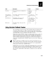
Page 91: ... gets a new IP address every time it is booted When Trakker Antares UDP Plus terminals are communicating with access points and the DCS 300 the Connect icon is on If the Connect icon blinks the terminal is no longer communicating with the DCS 300 If you have implemented the Auto Fallback feature in your data collection network simply press Ltwice on your terminal to obtain a new controller IP addr...

Page 92: ...any valid IP address For help see your terminal user s manual 2 Scan this bar code Enable DHCP D KNI1 NI1 3 Press Ltwice The terminal looks for a DCS 300 on the network When it locates a DCS 300 it resets its controller IP address parameter to the IP address of the DCS 300 that it found Note If the terminals are in a different subnetwork than the DCS 300 you must configure and enable the DHCP rela...

Page 93: ...etwork 3 25 3 Saving Your Runtime Configuration When you finish configuring your network adapter card you should save your changes To save your runtime configuration From the main screen sidebar buttons choose Save Configuration ...

Page 94: ...blank ...

Page 95: ...Connecting to the Intermec RF Network 4 ...

Page 96: ...DCS 300 System Manual blank ...

Page 97: ... 6 Y Set the time parameters for the 900 MHz RF network 4 10 Y Configure your UDP Plus network 4 18 Y Set the time parameters for the UDP Plus network 4 21 Y Configure your WTP network 4 31 Y Edit the JANUS 900 MHz device parameters 4 15 Y Edit the UDP Plus device parameters 4 27 Y Edit the WTP device parameters 4 38 If you already understand and have performed these tasks connect the DCS 300 to y...

Page 98: ...rom the DCS 300 to Intermec 900 MHz RF devices and receive signals from them The illustration on the next page shows an example of a DCS 300 connected to the Intermec 900 MHz RF network To connect the DCS 300 and the BRU Intermec provides you with a 4 port interface cable Insert one end of the cable into the port on the RF card Use the Intermec cable kit Part No 055003 or equivalent to connect to ...

Page 99: ...onnecting to the Intermec RF Network 4 5 4 Example The DCS 300 Connected to the Intermec 900 MHz RF Network R S 4 8 5 R S 4 8 5 RS 232 J2050 JR2020 3400 0300U016 eps 9450 9181 9181 9189 9465 Host DCS 300 ...

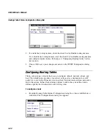
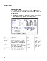
Page 100: ...ddress and a unique network ID To configure the RF card 1 From the main screen choose the type of host environment you are using to communicate between the DCS 300 and the host 2 Choose Downline Network Two buttons Connection Points and Downline Devices appear 3 Choose Connection Points The Connection Point List dialog box appears 4 Choose Add Edit or Delete If you choose Add the Add a Downline Co...

Page 101: ... default host for each type of host that the RF card devices will communicate with through the RF card For help see Defining Default Hosts later in this chapter 9 Choose OK The RF Card Devices dialog box appears For help see Defining the RF Card Devices later in this chapter 10 Choose Close to return to the Connection Point List dialog box 11 Choose Close to return to the main screen 12 Enable all...

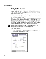
Page 102: ...r The RF card that you are configuring 1 1 RFNC address The unique radio frequency network address of the RF card Devices use this address to communicate with the BRUs attached to this card 0 to 63 0 If 0 is being used the next available value is used Network ID The unique network ID of the RF card Devices use this ID during a channel search to locate the RF card s RFNC address 1 to 254 1 If 1 is ...

Page 103: ...he number of seconds the DCS 300 waits to receive an acknowledgment after delivering a transaction to an RF device If it does not receive an acknowledgment the DCS 300 writes the transactions for the RF device to a Hot Standby file The RF device receives its transactions from this file when it comes back online 1 to 9999 40 Transactions held in volatile memory The number of transactions the DCS 30...

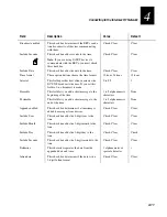
Page 104: ...ave a timestamp with the hour and minute You can also append the year month day and seconds Make sure that when you append the date and time to the incoming data the maximum transaction data length will not exceed 1024 bytes If the date and time that is appended is longer than the maximum transaction data length the time append will be truncated This feature will not operate when running terminal ...

Page 105: ...99 1 Preamble This field lets you add a short message to the beginning of the time 1 to 5 alphanumeric characters None Postamble This field lets you add a short message to the end of the time 1 to 5 alphanumeric characters None Append enabled This check box determines if a timestamp is added to messages from devices Check Clear Clear Include Year This check box adds the 4 digit year to the time Ch...

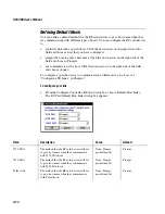
Page 106: ...se none To configure a specific device to communicate in a different way to a host see Configuring TE Links in Chapter 7 To configure your link From the Configure Controller RF card dialog box choose Default Host Links The RF Card Default Host Links dialog box appears Field Description Value Default 3270 SNA The method that the RF card devices will use to get a host name when they communicate with...

Page 107: ...logical name The base name that the DCS 300 uses to create a unique logical name for each device The DCS 300 appends a sequential 3 digit number to this name for each device 1 to 13 alphanumeric and special characters ISA1 Number of devices to enable The number of logical names that you want to enable to communicate through this RF card to the DCS 300 Each BRU supports 32 devices 4x32 128 1 to 128...

Page 108: ...pe transaction IDs and delivery responses Your DCS 300 can communicate with up to 254 devices The DCS 300 does not keep track of the number of devices you enable You can enable all devices As each device sends messages to the DCS 300 the DCS 300 logs its logical name When the DCS 300 logs 254 logical names it will not accept messages from any new logical names When you stop data collection on the ...

Page 109: ...k box 6 To disable all 128 devices choose Disable All Or to disable specific devices select the device you want to disable and make sure there is no check in the Enabled check box 7 Select a terminal whose individual parameters you want to edit and then choose Edit Device For help see Editing an RF Card Device in the next section 8 Choose OK to save your changes and return to the main screen Editi...

Page 110: ...vice if it cannot put a transaction ID in its transactions Note All transactions from this terminal will be routed using this transaction ID Predefined list None To be routed to device This field contains a transaction ID that will always be routed to this device Predefined list None Interactive response Optional The message that is sent to the source of the transaction if the transaction is deliv...

Page 111: ...s UDP Plus network Trakker Antares terminals such as the T2425 are terminals with network support The DCS 300 supports these terminals using Intermec s UDP Plus network Follow the instructions Configuring a UDP Plus Network later in this chapter JANUS UDP Plus devices such as the JG2020 are hand held data collection computers with network support The DCS 300 communicates with these terminals using...

Page 112: ...igure a UDP Plus network 1 From the main screen choose the type of host environment you are using to communicate between the DCS 300 and the host 2 Choose Downline Network Two buttons Connection Points and Downline Devices appear 3 Choose Connection Points The Connection Point List dialog box appears 4 Choose Add Edit or Delete If you choose Add the Add a Downline Connection Point dialog box appea...

Page 113: ...us Devices dialog box appears For help see Setting Up the UDP Plus Devices later in this chapter 10 Choose OK to return to the Connection Point List dialog box 11 Choose Close to return to the main screen 12 Enable all the UDP Plus devices that you want to communicate with the DCS 300 For help see Enabling the UDP Plus Devices later in this chapter Adding a UDP Plus Network After you finish config...

Page 114: ...us uses for communication This port must match the network port that is configured on the terminal 5001 to 65535 5555 Hot Standby Timeout The number of seconds the DCS 300 waits to receive an acknowledgment after delivering a transaction to a device If it does not receive an acknowledgment the DCS 300 writes the transactions for the device to a Hot Standby file The device receives its transactions...

Page 115: ...able this feature all messages have a timestamp with the hour and minute You can also append the year month day and seconds Make sure that when you append the date and time to the incoming data the maximum transaction data length will not exceed 1024 bytes If the date and time that is appended is longer than the maximum transaction data length the time append will be truncated You cannot use this ...

Page 116: ...no broadcast is made 0 to 99 1 Append enabled This check box determines if a timestamp is added to messages from terminals Check Clear Clear Include Year This check box adds a 4 digit year to the time Check Clear Clear Include Month This check box adds a 2 digit month to the time Check Clear Clear Include Day This check box adds a 2 digit day to the time Check Clear Check Include Seconds This chec...

Page 117: ...in Chapter 7 To configure your link From the UDP Plus Network Parameters dialog box choose Default Host Links The UDP Plus Default Host Links dialog box appears Field Description Value Default 3270 SNA The method that the UDP Plus devices will use to get a host name when they communicate with 3270 SNA hosts None Prompt pre defined list Prompt 5250 SNA The method that the UDP Plus devices will use ...

Page 118: ... the terminals and the DNS server resolves the IP addresses However you still need to enter the terminal s IP address on the terminal Enter each terminal s IP address manually If you do not use a DNS server you need to enter the terminal s IP address on the DCS 300 However the DCS 300 can help you generate logical names and IP addresses for the terminals You need to enter the number of terminals t...

Page 119: ...tarting IP address that the DCS 300 uses to assign IP addresses to each terminal The IP address must be a valid IP v4 address y x x x where y is a value between 1 and 223 not including 127 and x is a value between 0 and 255 None Domain The name of the domain that all of the terminals are in Note If you check the Use DNS check box and you do not enter a domain the DCS 300 searches the domains that ...

Page 120: ...m any new logical names When you stop data collection on the DCS 300 the logical name count is reset To enable the UDP Plus devices 1 From the main screen choose the type of host environment you are using to communicate between the DCS 300 and the host 2 Choose Downline Network Two buttons Connection Points and Downline Devices appear 3 Choose Downline Devices The Device List dialog box appears 4 ...

Page 121: ...ollow the next procedure Editing a UDP Plus Device 8 Choose OK to save your changes and return to the main screen Editing a UDP Plus Device This section explains how to edit many parameters for your UDP Plus terminal If you need to edit or resolve the IP address of the terminal see Determining a UDP Plus Device s IP Address or Editing a UDP Plus Device s IP Address later in this chapter To edit a ...

Page 122: ...l transactions from this terminal are routed using this transaction ID Predefined list None To be routed to device This field contains a transaction ID that will always be routed to this terminal Predefined list None Interactive response Optional The message that is sent to the source of the transaction if the transaction is delivered successfully to this terminal 1 to 40 characters None Hot stand...

Page 123: ...rver using the logical name If you did not enter a domain the DCS 300 searches the list of domains that are configured in the DNS Configuration dialog box Editing a UDP Plus Device s IP Address If you are not using a DNS server and you want to edit the IP address of a terminal from the Device Parameters dialog box choose Addressing The Device Address dialog box appears To edit a terminal s IP addr...

Page 124: ...oken ring network and WTP network The illustration below shows an example of the DCS 300 connected to the WTP network Example The DCS 300 Connected to the WTP Network Ethernet 1100 RT5980 Host 6400 Access point DCS 300 1100 RT5921 RT1700 Access point 6500 2 4GHz Synthesized UHF 1100 RT5960 6400 Access point 902 MHz Falcon 0300U068 eps U n i v e r s a l A c c e s s P o i n t U n i v e r s a l A c c...

Page 125: ...work Two buttons Connection Points and Downline Devices appear 3 Choose Connection Points The Connection Point List dialog box appears 4 Choose Add Edit or Delete If you choose Add the Add a Downline Connection Point dialog box appears 5 Choose WTP and then choose Add The WTP Parameters dialog box appears 6 Configure the WTP network For help see Adding a WTP Network in the next section 7 Define ho...

Page 126: ...ic host Click the down arrow on the right side of the field and choose a host that you have configured prompt the user to enter a host name Click the down arrow on the right side of the field and choose Prompt not communicate with a host Click the down arrow on the right side of the field and choose none To configure a specific device to communicate in a different way to a host see Configuring TE ...

Page 127: ...ice If it does not receive an acknowledgment the DCS 300 writes the transactions for the device to a Hot Standby file The device receives its transactions from the Hot Standby file when it comes back online 1 to 9999 40 RF host prefix A name for the DCS 300 that the DCS 300 uses to generate the host instances to support the WTP network 4 to 13 alphanumeric characters HOST Skip Unit Ready screen on...

Page 128: ... it is running a 5250 application None Predefined list Prompt Prompt Telnet The host that a WTP device connects to if the device is not explicitly linked to a host and it is running a Telnet application None Predefined list Prompt Prompt Native The port name and host that a WTP device connects to if the device is not explicitly linked to a host and it is running in Native mode None Predefined list...

Page 129: ...for each device 1 to 13 alphanumeric and special characters HOST About the RF Hosts Created for the WTP Network If you are adding a WTP network when you choose OK in the WTP Devices dialog box the RF Hosts Created for WTP dialog box appears This dialog box shows you the RF host instances that the DCS 300 has created You must assign each device to the RF host instance that you want it to communicat...

Page 130: ...ured with the RF host instance that it is using to communicate with the DCS 300 If you change the RF host name you must reconfigure each device with the new name To edit the WTP network 1 From the main menu choose the type of communications you are using to connect the server to the host 2 Choose Downline Network Two buttons Connection Points and Downline Devices appear 3 Choose Connection Points ...

Page 131: ...stop data collection on the DCS 300 the logical name count is reset To identify the WTP devices 1 From the main screen choose the type of host environment you are using to communicate between the DCS 300 and the host 2 Choose Downline Network Two buttons Connection Points and Downline Devices appear 3 Choose Downline Devices The Device List dialog box appears 4 In the Connection field click the do...

Page 132: ...c and special characters HOST000 Able to receive data This check box determines if this device can receive data from the network Check Clear Check Device type This list box contains all the current Intermec devices supported Predefined list Undefined Auto insert from device This field provides a transaction ID for this device if it cannot put a transaction ID in its transactions Note All transacti...

Page 133: ...his device 1 to 39 characters None Hot standby Optional The message that is sent to the source of the transaction if the transaction for this device is written to a Hot Standby file 1 to 40 characters None Saving Your Runtime Configuration When you finish configuring your downline network you should save your changes To save your runtime configuration From the main screen sidebar buttons choose Sa...

Page 134: ...blank ...

Page 135: ...Connecting to the 9180 and the Intermec CrossBar Network 5 ...

Page 136: ...DCS 300 System Manual blank blank ...

Page 137: ...CrossBar devices connected to controllers 5 20 Y Edit the CrossBar devices 5 22 Note In order for the 9181 Base Radio Units BRUs to communicate with a 9180 Network Controller that is connected to the DCS 300 you need to configure these BRUs using the 9180 configuration menu Refer to your 9180 user s manual If you already understand these sections and have already performed these tasks connect the ...

Page 138: ...or a 9154 Multi Drop Line Controller that is connected to the DCS 300 through a serial port The following illustration is an example of a DCS 300 connected to a 9180 and a CrossBar network Example The DCS 300 Connected to a 9180 and CrossBar Network RS 232 9154 9445 9560 0300U017 eps 3400 Host 9181 9181 9180 JR2020 JR2020 RS 232 DCS 300 ...

Page 139: ... appears 5 Choose the controller that you want to add and then choose Add The setup dialog box for the controller appears 6 Configure the controller For help see About the Controller Parameters in the next section and then see the appropriate section for your controller 7 Set any time parameters for the controller For help see Setting the Time Parameters later in this chapter 8 9180 v2 0 only Defi...

Page 140: ...erial port on the Intermec controller Time Parameters These optional parameters let you set time broadcast and time append parameters for the Intermec controller These time parameters synchronize the Intermec controllers with their devices In the System Parameters dialog box you can set a time synchronization parameter that synchronizes the time on the DCS 300 with its Intermec controllers For mor...

Page 141: ...ontroller to receive an acknowledgment for the transaction If it does not receive an acknowledgment the DCS 300 writes all transactions for the 9154 to a Hot Standby file The 9154 receives its transactions from this file either when it sends an acknowledgment to the most recently delivered transaction or when it sends a system transaction Before the 9154 becomes interactive again it receives all t...

Page 142: ...ant the transaction always written to the file Choose Unlimited if you do not want the transaction written to the file unless the time you set for the Hot Standby timeout expires Choose Maximum and enter a maximum number of transactions When the DCS 300 has this number of transactions in RAM it writes them to a file None Unlimited Maximum Maximum 50 Multi Drop Enabled The Multi Drop line that the ...

Page 143: ...ield Description Value Default Serial port The communications port to which the 9161 controller is connected COM1 COM2 COM1 Baud rate The baud rate at which the serial port communicates Predefined 9600 LRC enabled This check box determines if the longitudinal redundancy check character is appended to data transmitted by a device Check Clear Clear Parity The type of self checking to use when sendin...

Page 144: ...on as soon as it receives the transaction from the 9161 controller In Safer mode the DCS 300 acknowledges the transaction only after it is stored in a Hot Standby file Transaction throughput is slower because the DCS 300 cannot accept another transaction from the 9161 until it verifies the previous one Faster Safer Faster Transactions held in volatile memory The number of transactions the DCS 300 ...

Page 145: ... the 9180 controller is connected COM1 COM2 COM1 Baud rate The baud rate at which the serial port communicates Predefined 9600 LRC enabled This check box determines if the longitudinal redundancy check character is appended to data transmitted by a device Check Clear Clear Parity The type of self checking you want to use when sending data Even Odd None Even Data bits The number of bits to use for ...

Page 146: ...n the DCS 300 performs In Faster mode the DCS 300 acknowledges the transaction as soon as it receives the transaction from the 9180 controller In Safer mode the DCS 300 acknowledges the transaction only after it is stored in a Hot Standby file Transaction throughput is slower because the DCS 300 cannot accept another transaction from the 9180 until it verifies the previous one Faster Safer Faster ...

Page 147: ... the 9180 controller is connected COM1 COM2 COM1 Baud rate The baud rate at which the serial port communicates Predefined 9600 LRC enabled This check box determines if the longitudinal redundancy check character is appended to data transmitted by a device Check Clear Clear Parity The type of self checking you want to use when sending data Even Odd None Even Data bits The number of bits to use for ...

Page 148: ...n the DCS 300 performs In Faster mode the DCS 300 acknowledges the transaction as soon as it receives the transaction from the 9180 controller In Safer mode the DCS 300 acknowledges the transaction only after it is stored in a Hot Standby file Transaction throughput is slower because the DCS 300 cannot accept another transaction from the 9180 until it verifies the previous one Faster Safer Faster ...

Page 149: ...time at certain intervals to incoming data The timestamp is in the format HH MM SS If you want all messages to have a timestamp with the hour and minute enable this feature and set the interval to 0 Depending on your controller you can also append the seconds If no data is available within the interval the controller waits until it receives data and then appends the time before sending it to the h...

Page 150: ...DCS 300 User s Manual 5 16 To set the time parameters From any Configure Controller dialog box choose Time Parameters The Configure Time Parameters dialog box appears ...

Page 151: ...ostamble 9154 9180 only This field lets you add a short message to the end of the time 1 to 5 alphanumeric characters None Time format 9154 9180 only These option buttons choose the time broadcast format 12 hour 24 hour 12 hour Append enabled This check box determines if a timestamp is added to messages from devices Note Intermec recommends that you use the time append feature If you do not you ma...

Page 152: ...se none To configure a specific device to communicate in a different way to a host see Configuring TE Links in Chapter 7 To configure your link From the Configure Controller 9180 v2 0 dialog box choose Default Host Links The 9180 v2 0 Default Host Links dialog box appears Field Description Value Default 3270 SNA The method that the RF card devices will use to get a host name when they communicate ...

Page 153: ...box appears Field Description Value Default Base logical name The base name that the DCS 300 uses to create a unique logical name for each device The DCS 300 appends a sequential 3 digit number to this name for each device 1 to 13 alphanumeric and special characters COM1 Number of devices to enable The number of logical names that you want the DCS 300 to generate 1 to 128 8 ...

Page 154: ...nonexistent but enabled device your system performance will degrade Your DCS 300 can communicate with up to 254 devices The DCS 300 does not keep track of the number of devices you enable You can enable all 254 devices As each device sends messages to the DCS 300 the DCS 300 logs its logical name When the DCS 300 logs 254 logical names it will not accept messages from any new logical names When yo...

Page 155: ...specific devices select the device you want to enable and make sure there is a check in the Enabled check box 7 To disable all 128 devices choose Disable All Or to disable specific devices select the device you want to disable and make sure there is no check in the Enabled check box 8 Select a device whose individual parameters you want to edit and then choose Edit Device For help see Editing a Cr...

Page 156: ...eive data This check box determines if this device can receive data from the network Check Clear If the device has a screen it is checked else it is cleared Device type This list box contains all the current Intermec devices supported by the DCS 300 Predefined J2020 Physical address This read only field displays the physical address of the device Read only Predefined Auto insert from device This f...

Page 157: ... of the transaction if the transaction for this device is delivered successfully in Interactive mode 1 to 40 characters None Hot standby Optional The message that is sent to the source of the transaction if the transaction for this device is not delivered 1 to 40 characters None Saving Your Runtime Configuration When you finish configuring your downline network you should save your changes To save...

Page 158: ...DCS 300 System Manual blank ...

Page 159: ...Running Data Collection Browser 6 ...

Page 160: ...DCS 300 System Manual blank ...

Page 161: ...work together using Data Collection Browser dcBrowser This chapter describes how to configure your DCS 300 for using dcBrowser with your data collection devices Chapter Checklist Done Task Page Y Understand how dcBrowser runs between the Web server the DCS 300 and the data collection devices 6 4 Y Understand the environments 6 6 Y Set up the runtime environment 6 7 Y Configure and run dcBrowser in...

Page 162: ...vices get a Web page from the Web server each time they are turned on the devices are not running a client application that has to be upgraded You reduce project risk by using Web based middleware servers That is you can deploy a data collection network and retain the flexibility to change the back end system You use less bandwidth in your data collection network since the data collection devices ...

Page 163: ...ser gateway on the DCS 300 identifies the Web home page for this device The dcBrowser gateway requests this home page from the Web server 3 The Web server sends the requested Web home page to the dcBrowser gateway 4 The dcBrowser gateway interprets the Web home page creates a compressed data format and sends it to the device 5 Information from the device is sent to the dcBrowser gateway which conv...

Page 164: ...he HTML application You copy your application and Web pages to a Web server Then you load a Web browser and the simulator on your PC Using the Web server the Web browser and the simulator you can run your application The simulator contains a local dcBrowser gateway that runs on your PC and it simulates the dcBrowser gateway on the DCS 300 The simulator also simulates the device screens so you can ...

Page 165: ...gator 4 5 or higher not provided by Intermec DCS 300 v1 3 or higher Access points Data collection devices that are loaded with the dcBrowser client To set up the runtime environment 1 Verify that the DCS 300 is connected to and configured for your Ethernet network or token ring network For help see Connecting to an Ethernet Network or Connecting to a Token Ring Network in Chapter 3 2 Verify that t...

Page 166: ...ges to it For help see Starting the Web Server later in this chapter 5 Turn on your devices and start your application For help see the Data Collection Browser Client User s Guide Starting the dcBrowser Gateway Before you can map the dcBrowser devices you must start the dcBrowser gateway To start the dcBrowser gateway Access the DCS 300 Management Web page and then click the Start button after dcB...

Page 167: ... Web browser a button that contains the name Help appears When the user clicks this button the form processing sequence begins and the application tells the Web server HlpScrn1 Help If you enable the links feature the device displays a function key a greater than sign and the value that is the name of the button in a normal Web browser For example F1 Help When you press F1 the form processing sequ...

Page 168: ...lick dcBrowser Gateway The dcBrowser Gateway Configuration page appears 4 Enable or disable the links feature For more information about the links feature see the help 5 Expand the dcBrowser Gateway submenu and click Device Mapping The dcBrowser Device Mapping Configuration page appears ...

Page 169: ...65535 Most Web servers communicate on port 80 Instead of entering an IP address you can enter the host name of the Web server that the device will communicate with 8 In the Home Page field enter the Web page that the Web server sends to the device when the device is turned on You can enter a path to the Web page This path can have up to 64 alphanumeric characters 9 In the Device IP field enter the...

Page 170: ...Save Starting the Web Server Before you can run your application you must copy your application and Web pages to your Web server and start the Web server For help see the documentation that came with your Web server To run your application 1 Copy your EXE files to the CGI BIN directory for your Web server Note If you put your CGI scripts in a different directory than CGI BIN you may need to modify...

Page 171: ...Running Terminal Emulation 7 ...

Page 172: ...DCS 300 System Manual blank ...

Page 173: ... 7 Y For 5250 SNA TE configure the IBM SNA hosts and configure the DCS 300 to recognize all the hosts on the network 7 12 Y For 3270 SNA TE configure the IBM SNA hosts and configure the DCS 300 to recognize all the hosts on the network 7 18 Y For Native TE identify all the IP hosts on the network and make sure that your devices are running the TE application client 7 23 Y Configure any TE links 7 ...

Page 174: ...nds to move the smaller device screen around to see a much larger terminal screen Your DCS 300 is licensed to communicate with up to 254 devices When a device first sends a message through the DCS 300 the DCS 300 logs its logical name When the DCS 300 logs 254 logical names it will not accept messages from any new addresses 0300U026 eps Host Ethernet Token Ring SDLC IBM Host 3270 IBM Host 5250 Dat...

Page 175: ...ort Table VTXXX ANSI 5250 SNA 3270 SNA TN5250 TN3270 TE 2000 Native TE Sockets Trakker Antares terminal 1 Yes Yes Yes Yes No JANUS device 1 Yes Yes Yes No No WTP device VT220 Yes No No Yes Host Requirements TCP IP host that supports Telnet IBM SNA host e g AS 400 IBM host that supports Telnet2 TCP IP host that runs a Native server application 1 TCP IP devices do not need DCS 300 to run TE 2 When y...

Page 176: ... ANSI 5250 SNA and 3270 SNA Using TE 2000 you can run any TE by using the menu system to choose the emulation and the upline protocol However your keypad overlay usually supports only one of these TEs Trakker Antares UDP Plus terminals can also run Native terminal emulation to IP hosts through the Native sockets interface The terminals must have the dcBrowser client loaded on them For help see the...

Page 177: ...e you proceed make sure you have performed these tasks Installed the DCS 300 Configured the network adapter cards Installed and configured the downline connection points and data collection devices To configure an IP host 1 From the main screen choose Terminal Emulation 2 Choose IP Host The IP Terminal Emulation Configuration dialog box appears The list box contains the host names that you have co...

Page 178: ... dialog box choose Add Host The TCP IP Host Connection dialog box appears Field Description Value Default Host name The name that logically identifies the TCP IP host to the network 1 to 256 alphanumeric characters periods dashes None Use DNS This check box determines if you use a DNS server to resolve the IP address of this host Note To use DNS you first must configure a DNS server in the DNS Con...

Page 179: ...solves the IP address 4 Choose OK to save your changes and then return to the IP Terminal Emulation Configuration dialog box To configure the host IP address manually 1 In the Host name field enter the host name 2 Make sure the Use DNS check box is cleared 3 In the IP address field enter the host IP address 4 Choose OK to save your changes and then return to the IP Terminal Emulation Configuration...

Page 180: ... see Downloading the JANUS TE Application later in this chapter 2 Optional Configure each device to use the auto login feature For help see Using the Auto Login Feature later in this chapter 3 Optional Configure each device to display international characters For help see Displaying International Characters later in this chapter You are ready to run TE on your JANUS 900 MHz RF devices For help see...

Page 181: ...g on the type of communications your JANUS devices are using and which firmware version is loaded you can download the application to your JANUS devices using one of these methods If your JANUS 900 MHz RF device has firmware v3 01 or later use the download server feature For help see Using the DCS 300 to Transfer Files in Appendix A Note Your JANUS devices must have FTA EXE and FTA INI loaded on d...

Page 182: ...300 on the host unless you have the auto create controller turned on Configuring the DCS 300 To run 5250 SNA TE between JANUS devices Trakker Antares terminals and WTP devices and the host you must identify all the IBM SNA hosts Before you proceed make sure you have performed these tasks Installed the DCS 300 Configured the network adapter cards Installed and configured the connection points Use d...

Page 183: ...er 7 Check or clear the Use device names check box Note You must configure all Trakker Antares terminals and JANUS devices that communicate with the AS 400 host as virtual devices of the type 3197 WTP devices must be configured as virtual devices of the type 5291 Adding an IBM SNA Host You must identify any hosts you want the DCS 300 to communicate with for the terminal sessions When you add a hos...

Page 184: ...haracters DCS 300 network ID from the local SNA node definition Host LU The LU name that identifies the host This parameter must match the control point CP name or node name of the host 1 to 8 alphanumeric and special characters Host name Local PU Ethernet or token ring only A unique PU name for the host that allows the terminals to communicate with more than one host using the same upline adapter...

Page 185: ... appears Field Description Value Default Network ID The unique name of the SNA network This ID is used for problem notification 1 to 8 alphanumeric characters APPN Node name The name that other nodes use to address the DCS 300 This name is also the default LU and must be unique to the SNA network 1 to 8 alphanumeric and special characters ACCNET Node ID Specifies the last eight characters in the X...

Page 186: ...ulation Configuration dialog box select the host whose mode you want to set 2 Choose Mode The 5250 Terminal Emulation Mode dialog box appears 3 In the list box select the mode that you want to use 4 Choose Close to close the dialog box and return to the 5250 Terminal Emulation Configuration dialog box Setting and Removing the User ID and Password Your host may implement security at the session lev...

Page 187: ... host that has a user ID and password that you want to remove 2 Choose Security The 5250 Terminal Emulation Security dialog box appears 3 Choose Remove The host user ID and password are removed You return to the 5250 Terminal Emulation Configuration dialog box Performing a Double Pass Through on an IBM AS 400 Host Note To use this feature with 5250 SNA TE your AS 400 must be v2 3 or higher When us...

Page 188: ...must configure the host the DCS 300 and devices Configuring the Hosts For 3270 SNA TE your network administrator needs to set up the host to see the DCS 300 as an IBM model 3174 terminal controller Your network administrator also must provide all the NAUs host field LOCADDR that are set up on the host for the devices to use SDLC connections can be direct or through a modem If you are connecting to...

Page 189: ... of the hosts and explicitly link some terminals with hosts and NAUs You cannot link the NAUs in the pool For help see Filling the NAU Pool and Configuring TE Links later in this chapter Before you proceed make sure you have performed these tasks Installed the DCS 300 Configured the network adapter cards Installed and configured the connection points To configure the DCS 300 1 From the main screen...

Page 190: ...any SNA configurations Only one host connection is allowed for SDLC network adapter cards The DCS 300 maintains separate lists for 3270 SNA hosts and 5250 SNA hosts If you create a host when defining a 5250 terminal session you cannot use this host when defining a 3270 terminal session To add an IBM SNA host From the 3270 Terminal Emulation Configuration dialog box choose Add The Host Connection C...

Page 191: ...s change the host name on your terminal 8 uppercase alphanumeric or special characters The first character must be an alpha character SNA node name 2 digit suffix starting with 01 Address Ethernet or token ring only The LAN adapter address of the host For help see Converting Ethernet Addresses to Token Ring MAC Format in Appendix A Ethernet format or token ring MAC address format None Node ID Spec...

Page 192: ...ose NAU Pool The 3270 NAU Pool dialog box appears 2 Add all the NAUs to the NAU pool a In the New NAU field type in the NAU b Choose Add The NAU is added to the Unlinked NAUs pool 3 Remove any NAUs that you do not want to use a In the Unlinked NAUs pool select the NAU to remove b Choose Delete The NAU is removed from the pool 4 Choose Close to return to the 3270 Terminal Emulation Configuration di...

Page 193: ... to Native TE async hosts you may need to make some changes to your Native TE host applications so they work with the DCS 300 through the Native sockets interface For help updating your Native applications see the Native Terminal Emulation Programmer s Guide Part No 977 055 006 New feature You can now send the terminal session name the RF host stack number and the terminal number to the host In th...

Page 194: ...ou must understand stream sockets programming fundamentals An excellent reference book for sockets programming is UNIX Network Programming by W Richard Stevens ISBN 0 13 949876 1 Note Intermec does not provide application programming support for streams sockets programming The DCS 300 initiates communications with the host application through the configured port Individual terminal sessions are ma...

Page 195: ... name with a sign and the ports that have been configured for that host appear underneath it Double click on a host name with a sign and the ports for that host disappear 3 Choose Add Host Add Port Edit or Delete Note You cannot delete a host if it is linked to a device or a terminal session If you choose Add Host the TCP IP Host Connection dialog box appears For help see Adding a TCP IP Host late...

Page 196: ...The address that identifies the TCP IP host to the network This IP address must be a valid IP v4 address y x x x where y is a value between 1 and 223 not including 127 and x is a value between 0 and 255 None To determine the host IP address using DNS 1 In the Host name field enter the abbreviated or long host name If you enter the abbreviated name the DCS 300 searches the domain names in the DNS C...

Page 197: ...g an IP Port Note When you add an IP host a default port Telnet port number 23 is automatically added To add an IP port From the IP Terminal Emulation Configuration dialog box choose Add Port The Port Configuration dialog box appears Field Description Value Default Port name The name that identifies this port for this host The name must be unique for this host 1 to 8 alphanumeric characters None P...

Page 198: ...on Browser Client User s Guide Part No 070011 2 If they do not have the dcBrowser client loaded on them load the client For help see the Data Collection Browser Client User s Guide 3 Start data collection For help see Starting Data Collection in Chapter 2 4 Scan this bar code Run Program C DCBT24 BIN O OC ZDCBT24 BIN C DCBT24 BIN Or a On your terminal access the TRAKKER Antares 2400 Menu System b ...

Page 199: ...y a plus sign or a minus sign You can double click on a host with a sign and the ports that have been configured for that host appear underneath it You can double click on a host with a sign and the ports for that host disappear Unlinked Device State list box This list box contains a list of terminal sessions and devices that have not been linked to a host You can select multiple terminal sessions...

Page 200: ...l session of the device is started it will prompt the user to enter a host name Disable Session When the terminal session of the device is started it will not be able to connect to a host The terminal session is disabled To configure TE links 1 From the main screen choose TE Links The Terminal Emulation Links dialog box appears 2 Link any terminal sessions of the devices to hosts a In the Terminal...

Page 201: ...ose a terminal session from the Linked Terminal Sessions box it is now removed from the box and unlinked from the host The State column is Disabled 5 3270 SNA hosts only Edit any NAUs that the DCS 300 assigned when you explicitly linked the terminal session to a host a In the Linked Terminal Sessions box select the NAU that you want to change b Choose Edit NAU The Edit NAU Address dialog box appea...

Page 202: ... 2 4 GHz Installation Utility User s Manual For help setting a password on Trakker Antares terminals see the Trakker Antares Terminal Emulation User s Guide Note This feature is not supported on WTP devices To set security for the TE Configuration menu 1 From the main screen sidebar buttons choose System Maintenance The System Maintenance dialog box appears 2 Choose Terminal Password Configuration...

Page 203: ...ppears 3 To change a password on a terminal select the terminal or group of terminals from the Secured Terminals list box and choose Change The Terminal Password dialog box appears 4 In the Password field enter a new password to access the TE Configuration menu 5 Choose Change The password is changed 6 Choose Close to close the dialog box and return to the System Maintenance dialog box 7 Choose Cl...

Page 204: ...et 5 Choose Close to close the Runtime Configuration dialog box and return to the View Runtime Configuration Options dialog box 6 Choose Cancel to return to the System Reporting dialog box 7 Choose Close to return to the main screen Using the Auto Login Feature This feature enables the device to automatically log into the subsequent TE session if it loses a host connection When a terminal session ...

Page 205: ...ress 7 2 Select the Exit TE command and press The next time you start a TE session on the JANUS device you will need to log in again This method prevents another user from using your login Trakker Antares Terminals When the terminal session is started the terminal screen displays the host login prompt If you are using the auto login feature after you log into a host the terminal runs the auto logi...

Page 206: ... desired code page table MAP file to DISPTBLS MAP Refer to the table below 2 Download the new DISPTBLS MAP file to your device For help see Using the DCS 300 to Transfer Files in Appendix A 3 Modify the AUTOEXEC BAT and CONFIG SYS files on your device to display the international characters For help see your JANUS Terminal Emulation Quick Reference Guide Country Code Page Table Other Countries U S...

Page 207: ...P Italy 280 850 MAP Norway 277 850 MAP Denmark Portugal 500 850 MAP Belgium Brazil Switzerland Spain 284 850 MAP Sweden 278 850 MAP Finland Note To create a custom translation table for non IBM hosts running VT ANSI TE copy ISO1 850 MAP for UNIX hosts or DEC 850 MAP for DEC VAX hosts and rename the file to DISPTBLS MAP WTP Devices You may want to use an international character set with your WTP de...

Page 208: ...s if you need to reboot the DCS 300 To save and activate your runtime configuration 1 From the main screen sidebar buttons choose Save and Activate The Activate Configuration message box appears 2 Choose Activate The DCS 300 saves your runtime configuration to disk and it becomes your active configuration If you are ready to start data collection from the main screen sidebar buttons choose Start D...

Page 209: ...Running Peer to Peer Applications 8 ...

Page 210: ...DCS 300 System Manual blank ...

Page 211: ...ons so that they can communicate with the DCS 300 This chapter also provides guidelines on how to write applications that communicate using a direct TCP IP socket interface Chapter Checklist Done Task Page Y Configure the host for peer to peer applications 8 5 Y Identify the peer to peer links 8 6 Y Identify any transaction IDs that are routed to the peer to peer links 8 9 Y Save and activate the ...

Page 212: ... called NetComms NetComms are responsible for safely routing data from remote applications across a network to the DCS 300 and back After you configure the DCS 300 you need to create or modify your TCP IP and APPC applications so that they communicate with the DCS 300 If you need more information see the DCS 300 Technical Reference Manual Data Collection Network 0300027 eps Token Ring Twinaxial SD...

Page 213: ...CS 300 s logical unit name is the partner LU name that your application references when allocating an APPC conversation The default is ACCNET Network ID The network ID is the SNA network ID that was specified when you configured the DCS 300 The default is APPN MAC address The Ethernet or token ring address You can verify the default value using the View Runtime Configuration feature For help see V...

Page 214: ...he transaction ID and routes the transaction to all destinations in the peer to peer destination list that are associated with this transaction ID The application is the destination in the transaction header This section describes how to set up the peer to peer destination list for your host applications and your devices Before you proceed make sure you have already performed these tasks Installed...

Page 215: ... Hot Standby file 1 to 9999 20 Transactions held in volatile memory The number of transactions the DCS 300 keeps in RAM before it writes the transactions to a Hot Standby file Choose None if you want the transaction always written to the file This setting is the safest setting and it is also the slowest Choose Unlimited if you do not want the transaction written to the file unless the time you set...

Page 216: ...in Interactive mode 1 to 40 characters None Hot standby optional This message is sent to the source of the transaction when the transaction for this destination is written to a Hot Standby file 1 to 40 characters None Using International Text Pass Through International text pass through allows data streams representing characters encoded in various encoding schemes to pass without conversion betwe...

Page 217: ...DCS 300 still supports limited mapping from EBCDIC code page 037 to PC code page 437 If the DCS 300 cannot look up the source of the transaction in the peer to peer destination list the DCS 300 assumes that EBCDIC mapping is enabled and international text pass through is disabled However if you check the international text pass through check box you disable this EBCDIC mapping Mapping from arbitra...

Page 218: ...DCS 300 places the transaction in a Hot Standby file 1 to 40 characters None Delimiter The character that separates the fields in the transaction The delimiter must be the same throughout the network 1 alphanumeric or special character comma Adding a Transaction Field You need to add transaction fields if you are using these transactions for screen mapping To add a transaction field From the Trans...

Page 219: ... to reboot the DCS 300 To save and activate your runtime configuration 1 From the main screen sidebar buttons choose Save and Activate The Activate Configuration message box appears 2 Choose Activate The DCS 300 saves your runtime configuration to disk and it becomes your active configuration If you are ready to start data collection from the main screen sidebar buttons choose Start Data Collectio...

Page 220: ...box This figure shows a typical client server configuration using sockets Server 1 runs on Host 1 and Client 1 runs on Host 2 Server 1 listens on a socket that uses IP Each socket is identified by a socket address which is a data structure that specifies the address family network address and port number Address Family IP Network Address 192 5 7 9 Host 1 Host 2 0300U 029 Socket Socket APP 1 UDP TC...

Page 221: ...etComm is responsible for creating the application IPC channel and forwarding any data in that channel to the application The server receive NetComm is responsible for opening the Receive input channels of the message handler and for sending data that is received from the application through the network connection to the message handler When the DCS 300 is turned on it detects when TCP IP is being...

Page 222: ...ives a message from the DCS 300 your application must perform these steps 1 The application acknowledges the send NetComm with the NetACK 2 The application acknowledges the message handler as follows The application creates the ACK transaction by swapping the message s source and destination The transaction can contain data The application sets the fNetACK flag to A The application writes the ACK ...

Page 223: ... fNetACK flag 3 The application sends the transaction to the receive NetComm Because the fNetACK flag is clear the receive NetComm routes the transaction to the Receive channel which sends the transaction to the message handler Programming Interface for Applications to the DCS 300 DCS 300 Receive ACK 0300U 033 Hot Standby File Message Handler LAN_APP Recv NetComm Send NetComm Network Connection Ne...

Page 224: ...If you set the parameter to a small number only that many transactions can be lost during a power failure If you set the parameter to 0 no transactions are held in volatile memory Instead all transactions that would have been written to AUX_Q are instead written to a Hot Standby file When you configure the DCS 300 you must pick a realistic value for the Hot Standby timeout so that the DCS 300 does...

Page 225: ...evices already allow you to load a TCP IP stack To use the direct TCP IP socket interface the clients must use a special transaction ID IPT The DCS 300 recognizes this special transaction ID and starts these steps 1 A TCP IP client such as a JANUS device sends a transaction with the special transaction ID IPT 2 The server DevComm recognizes the special transaction ID and routes it directly to a me...

Page 226: ...P IP Socket Interface Message Handler ISM DCS 300 DevComm Network connection Remote LAN application IPD DCD 2 1 3 Devices TCP IP clients 0300U035 eps TCP IP network Access point 1 4 U n i v e r s a l A c c e s s P o i n t Tab 4 8 Tab 4 8 ...

Page 227: ... Hot Standby file are sent to the application destination when the host connection is re established When a direct TCP IP API socket connection goes down there is no data redundancy and the client or server application must re establish the connection and retransmit the last transaction With the direct TCP IP API only the client can initiate the connection Your host application must be a server ap...

Page 228: ...eceives a packet from the DCS 300 that acknowledges the request Client receives an OPEN_NAK negative acknowledgment packet from the DCS 300 which indicates the request to open a socket has failed Client receives an OPEN_ACK acknowledgment packet from the DCS 300 which indicates the request to open a socket has succeeded Client sends and receives data to and from the host through the DCS 300 The da...

Page 229: ...0 attaches a transaction header to messages that it receives from hosts and it attaches a transaction ID to route messages to and from devices The text for the transaction header and the transaction ID are limited to what you can enter on the DCS 300 The text for the transaction data can be an arbitrary sequence of bytes representing text in any character encoding scheme Configuration text that is...

Page 230: ...end application must act as a send requester It can send transactions to the DCS 300 without being configured in the DCS 300 because the DCS 300 will never send anything to it The source application ID field in the transaction header is always blank Note The DCS 300 s APPC receive NetComms only receive data in a maximum of 1120 byte chunks 96 bytes transaction header 1024 bytes data If more than 1...

Page 231: ...RROR MC_CONFIRM CONFIRM CONFIRM MC_CONFIRMED FLUSH FLUSH MC_DEALLOCATE DEALLOCATE ABEND MC_RECEIVE_AND_WAIT NONE RECEIVE_ALLOCATE MC_REQUEST_TO_SEND IMS Applications Older IMS applications before version 4 0 do not support the MC_CONFIRMED or MC_SEND_ERROR verbs Since IMS applications do not support these verbs applications must send an acknowledge transaction back to partner programs by setting t...

Page 232: ...blank ...

Page 233: ...Running Terminal Sessions 9 ...

Page 234: ...DCS 300 System Manual blank ...

Page 235: ...ons on the DCS 300 You can use these terminal sessions for running screen mapping as explained in Chapter 10 Running Screen Mapping Chapter Checklist Done Task Page Y Configure the host for terminal sessions 9 5 Y Configure the VT terminal sessions on the DCS 300 Or 9 7 Y Configure the 5250 terminal sessions on the DCS 300 Or 9 12 Y Configure the 3270 terminal sessions on the DCS 300 9 17 Y Save a...

Page 236: ... the DCS 300 to access your host directly from the DCS 300 By accessing your host you can verify your host connection and you can start remote applications You can also use these sessions as screen mapping sessions For help see Chapter 10 Running Screen Mapping Data Collection Network 0300038 eps Token Ring Twinaxial SDLC IBM Host IBM Host Ethernet TCP IP Host DCS 300 ...

Page 237: ...port The total number of sessions is the sum of all of the terminal session types You can have 100 VT100 sessions and 128 VT220 sessions but you cannot have 228 VT100 sessions and 228 VT320 sessions Terminal Session Type Total Number of Sessions VT100 VT220 VT320 ANSI 228 TN3270 TN5250 3270 SNA 26 5250 SNA 15 Setting Up 5250 Terminal Sessions Using SDLC If you are setting up 5250 terminal sessions...

Page 238: ...parameter when configuring the DCS 300 Setting Up 3270 Terminal Sessions Using SDLC If you are setting up 3270 terminal sessions over an SDLC link your network administrator needs to create a controller and then a display on the host When configuring the SDLC adapter card you need to know these parameters The station address 2 digit hexadecimal number The attached non switched line which is the li...

Page 239: ...med these tasks Installed the DCS 300 Configured the network adapter cards Installed and configured the downline connection points and data collection devices To create a terminal session 1 From the main screen choose Terminal Session 2 Choose Host Connection The Terminal Session List dialog box appears 3 Add edit or delete terminal sessions For help see Adding a Telnet Terminal Session Adding a 5...

Page 240: ...terminal mode that you want to use for this terminal session VT100 VT220 VT320 ANSI TN5250 TN3270 VT220 Host Name The name of the TCP IP host to which the terminal session connects For help adding a host see Adding a TCP IP Host in the next section Predefined None Number of sessions The number of terminal sessions that you want to run on the DCS 300 1 to 228 1 Port number The port number that this...

Page 241: ...None Use DNS This check box determines if you use a DNS server to resolve the IP address of this host Note To use DNS you must first configure a DNS server in the DNS Configuration dialog box Check Clear Clear IP address The address that identifies the TCP IP host to the network This IP address must be a valid IP v4 address y x x x where y is a value between 1 and 223 not including 127 and x is a ...

Page 242: ...ng the VT Terminal Setup When you add a new VT or ANSI terminal session and then you choose OK a message box appears asking if you want to use the Default or Custom VT terminal setup If you choose Default you return to the Terminal Session List dialog box If you choose Custom the VT Setup dialog box appears If you have already created a terminal session and you want to edit the fields in this dial...

Page 243: ... margin the terminal displays each new character in the last column of the line Each new character overwrites the previous character Check Clear Clear Controls Defines the type of control characters that your terminal uses Choose 7 bit if you want the terminal to use all the VT320 features Choose 8 bit if you want the terminal to support 8 bit graphic display characters and 7 bit control character...

Page 244: ...A network For help see Configuring the SNA Local Node later in this chapter To add a 5250 SNA terminal session From the Terminal Session List dialog box choose 5250 SNA The Terminal Session Definition dialog box appears Note If you set a password and you choose OK and leave this dialog box the Show check box does not appear if you edit this session To change your password delete all the asterisks ...

Page 245: ... that need a larger session limit up to 254 This mode unlike the other ones in the predefined list is not a default mode and your network administrator will have to create it on the host For more help on ACCNET see the DCS 300 Technical Reference Manual Predefined INTER Host user ID The user ID that lets you log into the host 1 to 10 alphanumeric characters first character is alpha None Password T...

Page 246: ...A configurations If you delete a terminal session the host name associated with that session still exists Only one host connection is allowed for twinaxial and SDLC network adapter cards The DCS 300 maintains separate lists for 3270 SNA hosts and 5250 SNA hosts If you create a host when defining a 5250 terminal session you cannot use this host when defining a 3270 SNA terminal session To add an IB...

Page 247: ...definition Host LU The LU name that identifies the host This parameter must match the control point CP name or node name of the host This name is known throughout the SNA network 1 to 8 alphanumeric and special characters Host name Local PU TE only A unique PU name for the host that allows the terminals when running TE to communicate with more than one host using the same upline adapter card 8 upp...

Page 248: ...ption Value Default Network ID The unique name of the SNA network This ID is used for problem notification 1 to 8 alphanumeric characters APPN Node name The name that other nodes use to address the DCS 300 This name is also the default LU and must be unique to the SNA network 1 to 8 alphanumeric and special characters ACCNET Node ID Specifies the last eight characters in the host XID that are used...

Page 249: ...l Session Definition dialog box appears Field Description Value Default Session name A meaningful long session ID that identifies this terminal session 1 to 8 alphanumeric characters None Short session ID The alpha identifier for this terminal session 1 alpha character A or the next open alpha character Host Name The name of the host to which the terminal session connects For help adding a host se...

Page 250: ...system Once you create a host connection you may use it for any SNA configurations If you delete a terminal session the host name associated with that session still exists Only one host connection is allowed for twinaxial and SDLC network adapter cards The DCS 300 maintains separate lists for 3270 SNA hosts and 5250 SNA hosts If you create a host when defining a 5250 SNA terminal session you canno...

Page 251: ...same upline adapter card 8 uppercase alphanumeric or special characters The first character must be an alpha character SNA node name 2 digit suffix starting with 01 Address Ethernet or token ring only The LAN adapter address of the host For help see Converting Ethernet Addresses to Token Ring MAC Format in Appendix A Ethernet format or token ring MAC address format None Node ID Specifies the last ...

Page 252: ...ption Value Default Network ID The unique name of the SNA network This ID is used for problem notification 1 to 8 alphanumeric characters APPN Node name The name that other nodes use to address the DCS 300 This name is also the default LU and must be unique to the SNA network 1 to 8 alphanumeric and special characters ACCNET Node ID Specifies the last eight characters in the host XID that are used...

Page 253: ...on from the main screen sidebar buttons choose Start Data Collection Starting a Host Session You can start host sessions between the DCS 300 and your host Use the session on the DCS 300 to access your host directly from the DCS 300 By accessing your host you can verify your host connection and you can start remote applications If you have purchased screen mapping you can use these sessions to retr...

Page 254: ... To use the diagrams 1 Locate the keyboard diagram for your application 2 On the keyboard diagram locate the function you want to perform and note its position on the key 3 Using the key combination legend below the diagram find the function s position on the key column and row 4 Press and hold the key from the legend and then press the key that performs the action For example you are running VT A...

Page 255: ...9 VT ANSI Terminal Keyboard Key Combination Legend Shift Base PF1 7 4 1 2 5 8 PF2 PF3 9 6 3 Enter PF4 Delete Return 0300U 039 Ctrl F11 F11 F12 F13 F14 F15 Help F16 Do F17 F18 F19 F20 F10 Ctrl H Find Remove Select Next Scrn Prev Scrn ...

Page 256: ...Shft Reset Reset NumLk NumLk NumLk Kp7 Home TOPPAG Kp4 CurLf BEGLIN Kp1 Dup BOTPAG Kp0 InsertT Kp2 CurDn BOTPAG Kp5 Kp8 CurUp TOPPAG KpComa Kp9 PageUp Kp6 CurRt ENDLIN Kp3 PageDn KpPeri Delete Enter Enter Tab FLD CR _ FLD CR PrtH PrtP SysReq Help Help ImmRst Clear Clear TstReg FldEx FldEx BckSpc BckSpc RQBS NewLne Enter CR Rshft Rshft 0300U 040 ...

Page 257: ...tWin NxtWin CapsLk CapsLk CapsLk LShft LShft Reset Reset PrCncl NumLk NumLk NumLk 7 Home 4 CurLf 1 End Paste Insert 2 CurDn 5 8 CurUp Space RVideo 9 6 CurRt Undr Sc 3 FlHigh Cut Refrsh Delete DelWd Copy Enter Enter Tab Print SysReq ScrLk Restrt ScrLk PrCtrl Clear Enter Enter BckSpc BckSpc Undo NewLne NewLne Rshft Rshft 0300U 042 ...

Page 258: ...DCS 300 System Manual 9 26 blank ...

Page 259: ...Running Screen Mapping 10 ...

Page 260: ...DCS 300 System Manual 10 2 blank ...

Page 261: ...Chapter Checklist Done Task Page Y Create a new or open an existing script file 10 17 Y Set global options for the current script 10 22 Y Create standard sequences for starting and ending screen mapping sessions 10 26 Y Define all transactions that the current script uses 10 31 Y Select a current transaction 10 31 Y Define all the host screens that receive data from the current transaction 10 32 Y...

Page 262: ...DCS 300 User s Manual 10 4 Chapter Checklist continued Done Task Page Y View and check the script 10 58 Y Map the transaction fields to the host screen fields 10 68 Y Save the configuration 10 69 ...

Page 263: ...apping sessions allow multiple terminal sessions on the DCS 300 to simultaneously communicate with multiple terminal emulator sessions running on different hosts To create an application that runs on your devices For Trakker Antares terminals you can use the C programming language Intermec recommends that you use EZBuilder which is a fast easy to use development tool that creates applications You ...

Page 264: ...a host application running in a terminal emulator Typical Screen Mapping Application 0300U 045 Work Order 1 Part 6020 Quantity 200 Order Due Date 040996 Lot Number LN609820 Add Part Number Press enter to save WO 1 TRX Part 6020 Qty 200 ORD DATE 04 09 96 9181 AN TE NN A PO WE R RF NC RX TX Bas e Rad io RF NC Host Screen ...

Page 265: ...uilder Tool Before you start using the Script Builder Tool you should identify the tasks that you want the script to perform You must know the transactions that the script will process You should also design one terminal screen for each transaction the starting point host screen for all transactions If the script is going to handle only one transaction the main host screen is the screen that conta...

Page 266: ...ill notice that when the script file maps the transaction it always starts from the main host screen It returns to the main host screen after it maps the last transaction field You need to consider how much time it takes to get from the main host screen to the first host screen that receives the first transaction field mapping Each type of script file has advantages and disadvantages Generally it ...

Page 267: ...ltiple Transaction Script vs Single Transaction Script Example Main host screen Screen 1 Screen 2 Screen 3 First mapping screen Screen 4 Screen 5 Back to Screen 1 Main host screen First mapping screen Screen 4 Screen 5 Back to Screen 4 ...

Page 268: ...ure your script file Example 1 Single Transaction Script File In this example the script file will log on to the AS 400 and invoke an MRP application called Data 3 Systems to add a work order This task will be performed using one transaction To complete the work order add transaction a user will need to enter the work order part number in Screen 4 and the quantity and order due date in Screen 5 Th...

Page 269: ...Running Screen Mapping 10 11 10 Screen 3 Screen 4 Main Host Screen Screen 5 ...

Page 270: ...l go to Screen 6 to process the work order quantity inquiry transaction Screen 3 is the central starting point for both transactions and therefore it is the main host screen The work order quantity inquiry transaction requires you to enter the work order in Screen 6 to start the inquiry Therefore the Work Order field will require the script file to map transaction data to it Screen 7 shows the res...

Page 271: ...Running Screen Mapping 10 13 10 Screen 4 Menu Option 915 Screen 5 Screen 6 Menu Option 910 Screen 7 ...

Page 272: ...the current screen The script maps transaction fields to these fields 5 Region List Choose Screen and then Region List Define the regions for the current screen Regions can handle errors on the host screen and they can output data 6 Next Screen Choose Screen and then Next Screen Define the next host screen This host screen becomes the current screen Go to Step 4 1 in the flow chart to define field...

Page 273: ... 10 15 10 Script Builder Tool Flow Chart n o Normal Logoff Sequence Abnormal Logoff Sequence New Script Logon Sequence Define Main Host Screen Select Transaction Define Fields Define Regions Define Next Screen Save Script p ...

Page 274: ...ession if you want to get host attributes from the host screen From the main screen choose Screen Mapping and then Script Builder The Script Builder Tools window opens All of the toolbar buttons for the major script building tasks are considered primary or configuration buttons These buttons contain a check mark in the upper right corner such as the New Open button All buttons for secondary or mai...

Page 275: ...e of the script you are creating or opening 1 to 8 alphanumeric characters and underscores None Description Optional A paragraph of text that describes the script 1 to 255 characters None Session ID Optional The session ID that you want to use when creating this script Note This temporary host session does not have to be the same host session as the runtime screen mapping session you associate wit...

Page 276: ...down arrow on the right side of the field A list of session IDs appears Choose a session ID Note If you have started data collection on the DCS 300 you cannot choose any session that is currently being used 5 Optional Choose Start Session The host window opens 6 Choose OK to return to the Script Builder Tools window Saving the Script File You should periodically save your script file while you are...

Page 277: ... Save Script As dialog box appears 6 In the Script name field enter a unique name for the new script Or click the down arrow on the right side of the field A list of existing script names appears Select one 7 In the Description box enter a new description for the script 8 To assign new transactions to the new script check the Use different transactions check box The Save As Script With Different T...

Page 278: ...d and new transaction names appear in the Old Transaction Name New Transaction Name list box 10 If you want to restore the old transaction name or if you want to choose another new transaction name select the old transaction name from the Old Transaction Name New Transaction Name list box and choose Restore Old Name 11 Choose OK to save the script to disk and to return to the Script Builder Tools ...

Page 279: ... Delete Script dialog box appears 3 In the Script name field click the down arrow on the right side of the field A list of existing script files appears Select the script you want to delete 4 Choose OK to delete the script A message box appears confirming that you want to delete the script 5 Choose Delete The script is deleted ...

Page 280: ...Response timeout Sets the number of minutes that the DCS 300 waits for a host busy condition to clear 1 to 99 2 Reset on timeout This check box determines if the DCS 300 sends a Reset key to the host if the host is busy Check Clear Check Error retries These option buttons determine if the DCS 300 retries the connection and how many times it retries the connection to the host application when an er...

Page 281: ...heck Send to source when batch transaction received This check box determines if the DCS 300 sends a message to the source of the transaction when the last transaction is received in batch mode Note If the Process batch transactions check box is cleared this check box is grayed out Check Clear Check Audit Options Determines the level of auditing the DCS 300 performs If you enable auditing when a n...

Page 282: ...he TCP IP socket and if there is no activity and the timeout period expires the DCS 300 performs the next action However there is no guarantee that the host is finished sending data Note The DCS 300 may not wait the entire timeout period if an action is performed successfully For example the PUT_TRANS_FIELD command waits until the cursor is at the field location or it may wait for the data respons...

Page 283: ... host screen that receives all transactions for this script such as the main host screen Normal logoff sequences are keystrokes that exit the host application from the main host screen Abnormal logoff sequences are keystrokes that exit the host application from any host screen Abnormal logoffs usually occur when the DCS 300 encounters a critical error Before you can capture keystrokes you need to ...

Page 284: ... Logon Sequence dialog box appears Note If you do not want to capture the logon keystrokes you can type them into the Selected Keystrokes field Go to Step 6 3 Choose Start 4 In the host window enter the keystrokes you want to use for your logon The Script Builder Tool captures all the keystrokes that you type 5 When you finish entering the keystrokes for the logon choose Stop The keystrokes you ty...

Page 285: ... to use as the main screen For help see Adding a Host Screen later in this chapter 8 Choose OK to return to the Script Builder Tools window Example Keystrokes Appearing in Logon Sequence USERID Enters the login name USERID in the User ID field RTAB Tabs to the Password field PASSWORD Enters the password Password This password goes with the login name ENTER Presses Enter to enter the information fr...

Page 286: ...ture the normal logoff keystrokes you can type them into the Selected Keystrokes field Go to Step 6 3 Choose Start 4 In the host window enter the keystrokes you want to use for your normal logoff The Script Builder Tool captures all the keystrokes that you type 5 When you finish entering the keystrokes for the normal logoff choose Stop The keystrokes you typed appear in the Captured Keystrokes box...

Page 287: ...strokes that exit you from the host application from any host screen Abnormal logoffs usually occur when the DCS 300 encounters a critical error Note Some host applications may not allow abnormal logoff sequences To create an abnormal logoff 1 From the Script Builder Tools window choose Host Access 2 Choose Abnormal Logoff The Abnormal Logoff Sequence dialog box appears Note If you do not want to ...

Page 288: ...capture keystrokes you can type them into the Selected Keystrokes field and then choose Before or After Deleting Lines in the Captured Keystrokes Box You can either delete your keystrokes one line at a time or you can delete all the keystrokes you have captured and start over again To delete one line 1 In the Captured Keystrokes box select the line that contains the keystroke that you want to dele...

Page 289: ...ld Using the Script Builder you can map each transaction field to a host screen field Therefore you need to choose a current transaction before you can define any host screens host screen fields or regions for that transaction In the Selected list box select the transaction whose fields you want to map to host screen fields and then choose Current To select the transactions for the script From the...

Page 290: ...ion The current host screen is the host screen for which you are currently defining fields regions messages and events When you define the main host screen it automatically becomes the current host screen If you add more host screens the main screen remains the current host screen until you go to the Maintain Screen List dialog box select a screen and then choose Current ...

Page 291: ...n Note Before you can use the capture keystrokes feature you must start a temporary host session For help see Starting a Host Session in Chapter 9 To define the next screen sequence 1 From the Script Builder Tools window choose Screen 2 Choose Next Screen The Next Host Screen dialog box appears This dialog box is shown on the next page Note If you do not want to capture the keystrokes you can type...

Page 292: ...t the host screen that you want to follow the Current screen Or to define a new host screen for the next screen choose New For help see Adding a Host Screen later in this chapter 8 Optional Choose Next if you want to make the next screen the current host screen The Script Builder displays the next screen information 9 Repeat Steps 3 through 8 to define the entire next host screen sequence for the ...

Page 293: ...x displays all of the fields that are defined for the current host screen their location in the host screen and whether they receive their data from a transaction field or a static string 3 Add edit or remove fields for the current host screen For help see Adding a Host Screen Field later in this chapter Note If you try to delete this host screen field and other transactions map fields to it it is...

Page 294: ...ation but you must add the mapping type and keystroke to exit field Get Field button If you started a temporary host session for this script you can use the Get Field feature to automatically detect the location of the field On the host window position your cursor on the first character of the field Choose Get Field The Row Column and Length fields are filled with values For help see Getting Host ...

Page 295: ...mapped to the host screen field Use this option if the data for the host screen field is mapped from a transaction field sent by a terminal Select new to define a new transaction field number Script Builder creates a new field with the host screen field label You can edit this transaction field later For help see Adding a Transaction Field in Chapter 8 Predefined new Static string The string that ...

Page 296: ...oose Get Field The Script Builder fills in the Location box with the beginning position of the field and its length VT ANSI host screens are not field formatted host screens To get host screen field attributes from a host screen field you must highlight the entire host screen input field before you choose Get Field If nothing is selected when you choose Get Field an error message occurs To get hos...

Page 297: ...en field You define the location and the length of the region To define the length you choose the Match on Any String within x characters field The script file sends any data that it finds in the location back to the application that is running on the terminal through a message To select a region 1 From the Script Builder Tools window choose Screen 2 Choose Regions The Host Screen Region List dial...

Page 298: ... at the main host screen you should choose to cancel processing the screen event When an error message occurs you usually want to return to the main host screen and process the next transaction If a region does not appear you can send a message to the source of the transaction Get Region button If you started a temporary host session for this script use the Get Region feature to automatically sele...

Page 299: ...e part of a group of regions that share the same action in the Actions for Region NOT appearing box This action only occurs if none of the regions in the group appear 1 to 8 alphanumeric characters and underscores None Row The row position on the host screen of the first character of the region 1 to 24 24 Column The column position on the host screen of the first character of the region 1 to 80 80...

Page 300: ...rs For help defining the keystrokes see Capturing Keystrokes later in this chapter Check Clear Clear Screen sequence Determines what event happens when the region is finished performing its actions Continue processing screen events Cancel processing screen events Go to next screen Continue processing screen events Continue processing screen events This option button indicates that the script file ...

Page 301: ...e protected fields When you choose Get Region the Script Builder fills in the Location box with the host cursor position and it fills in the contents and length of the field from the host cursor position to the end of the field VT ANSI host screens are not field formatted host screens To get region attributes you must highlight the entire region before you choose Get Region If nothing is selected ...

Page 302: ...g box appears Note If you do not want to capture the keystrokes you can type them into the Selected Keystrokes field Go to Step 6 3 Choose Start 4 In the host window enter the keystrokes to clear the region The Script Builder Tool captures all the keystrokes that you type 5 When you finish entering the keystrokes choose Stop The keystrokes you typed appear in the Captured Keystrokes box 6 If neces...

Page 303: ... file to return to the main host screen Note Before you can use the capture keystrokes feature you must start a temporary host session For help see Starting a Host Session in Chapter 9 To define the next screen sequence for a region appearing 1 From the Host Screen Region Definition dialog box choose the Go to next screen option button 2 Choose Screen The Next Host Screen dialog box appears Note I...

Page 304: ...ssage List from the Script Builder Tools the Screen Message List dialog box displays all the messages that are defined for the current host screen Sending screen messages is a screen event sending region messages is not an event If you define a screen message it is sent to the source of the transaction while the script file is processing screen events In the Screen Event Ordering dialog box you ca...

Page 305: ...Adding a Message later in this chapter 4 To use a message as a screen message select the message and check the Send message as current screen event check box To use a message as a region message do not check the Send message as current screen event check box When you define the region where you want to use this message select this message from the Send message drop down list box 5 Choose Close to ...

Page 306: ...s in the status line of your terminal Transaction message This message contains its data in the format of a transaction The transaction fields are mapped to the terminal screen fields according to the template Note To receive either type of message you must check the Wait for response check box when you are defining your terminal screen If you do not check this option the terminal will not read th...

Page 307: ...ransaction enter the transaction data You need to separate the transaction fields using the delimiter you set earlier when you defined your transactions This delimiter is usually a comma 1 to 120 characters None None This option button indicates that nothing from the host screen is included in the message Check Clear Check Region This option button indicates that a region is included in the messag...

Page 308: ...eld number 2 You also need to define a region QTY_RESULT on the Part Number Quantity host screen at the Quantity field Define a message and Quantity and then choose Transaction In the Text field enter 1 QTY_RESULT where 1 means that transaction field number 1 contains the same value as the original transaction field 1 is the transaction field delimiter QTY_RESULT is the region that you defined The...

Page 309: ...vents include mapping terminal transaction fields to host screen fields handling regions in the host screen sending screen messages The events listed below are not screen events and you cannot change the order in which they occur They are going to a next screen Next screen allows the script to go to another host screen after finishing all the screen events sending region messages Region messages a...

Page 310: ...hoose Event Order The Screen Event Ordering dialog box appears 3 In the Screen Events list box select the region that you want to move 4 Choose Up or Down to move the region to the appropriate place 5 Choose OK to return to the Script Builder Tools window Note Regions that match on a specific string are checked before regions that match on any string You may need to be aware of this feature if you...

Page 311: ...message box appears Note You cannot delete or remove the main host screen from the Selected Screens list box To delete or remove the main host screen you must edit the Logon Sequence dialog box and select a new main host screen If you want to define host screen fields and regions for a different host screen you can also select a new current host screen and choose Current The description of the scr...

Page 312: ... any string on a host screen that makes the host screen unique Get Field button If you started a temporary host session for this script you can use the Get Field feature to automatically select the location and contents of the screen identification On the host window position your cursor on the first character of the field Choose Get Field The Row Column and Screen ID fields are filled with values...

Page 313: ... anywhere in a protected field and then choose Get Field The Script Builder fills in the Screen Identifier box with the current host cursor position and it fills in the contents and length of the field from the host cursor position to the end of the field If the host cursor is in an unprotected field when you choose Get Field an error message occurs 3270 field formatted host screens do not differe...

Page 314: ...e For help see the DCS 300 Technical Reference Manual Note If you open and then save your script file in any text editor the Script Builder Tool will no longer recognize the file However you can still use your script file for screen mapping When you open the User Block List dialog box you may see these symbols to the left of lines in the script A plus sign indicates places where you can enter user...

Page 315: ...ore your user block The Tab key will only shift the focus to the next control The Script Builder Tool stores the user blocks in certain data structures so that it can reload them when the script file is closed and then reopened If you delete a data structure you may lose any user blocks that are associated with it For example you add a user block BLOCK1 that contains a comment after a specific PUT...

Page 316: ...ew Script feature displays the transactions as the top level in the script structure You can expand the transaction level to see the host screens that receive data from the transaction You may see these symbols in the script A plus sign indicates where you can expand the script A minus sign indicates where you can collapse the script To view the script 1 From the Script Builder Tools window choose...

Page 317: ...ndicates that more information is underneath the heading that is collapsed 3 Double click on a line with a on the left side to expand it Or double click on a line with a minus on the left side to collapse it 4 Choose Collapse All to collapse all lines that are expanded 5 Choose Close to return to the Script Builder Tools window ...

Page 318: ...le Logic in the next section Note You can also check your script file syntax in the Screen Mapping Session Definition dialog box To check for correct syntax 1 From the Script Builder Tools window choose Script 2 Choose Check Script The script checker checks the current script for syntax errors The DCS 300 View Results window appears listing the errors that the script checker found Refer to the exa...

Page 319: ...ifferent sets of data and you should test as many scenarios as possible Note When testing VT script files watch for timing problems Part 1 To verify the logic of a script file 1 Set up your test environment Note If you already have started a host terminal session make sure that the host terminal session is at the logon screen a Add a screen mapping session for the script file Select all the transa...

Page 320: ...een sent before the sign on screen appears Add logic to the script file so that it waits for the sign on screen before it sends the logon sequence For example see VTDEMO SCR in the USERDATA SCRIPTS directory on the DCS 300 Part 2 To verify the logic of a script file 1 Open testing and viewing tools a From the System Maintenance dialog box open the Send Transaction dialog box b From the System Main...

Page 321: ...file is stuck in a host screen and cannot finish processing the transaction data Make sure that the keystrokes that you captured that move you from one host screen to the next screen are correct Nothing happens on the host screen Make sure that you entered the correct transaction ID in the Send Transactions dialog box Make sure that the transaction ID you entered is listed in the Selected list box...

Page 322: ...adjust the region order VT only The script file does not catch the region even though you can see it on the host screen Due to the timing problem that occurs when the script file is executed faster than the host response time the script file might check the region before the host sends the error message to the terminal screen In the script file add a PAUSE statement before the IF_REGION so the scr...

Page 323: ...session Named each script you want to use Each script may use many transactions To send transactions to a different host using the same script file you define another screen mapping session that connects to the appropriate host session Defined the transactions you want to route to each host terminal session using the script file To set up a screen mapping session 1 From the main screen choose Scre...

Page 324: ...applications However you should not use this feature when you actually run your application because it will affect the DCS 300 performance If you check this check box the host terminal session opens when you start data collection Then you can watch your host screen fields being filled in as they receive transactions from the DCS 300 Start session at data collection start check box You may want to ...

Page 325: ...tart data collection Check Clear Check Hot Standby timeout The number of seconds the DCS 300 waits for a response from the data collection device before it places the device in Hot Standby mode 1 to 9999 20 Script File The name of the script file that this screen mapping session uses Predefined None Host Terminal Session The long session ID of the terminal session that this screen mapping session ...

Page 326: ...f you insert the WAIT_FOR_LABEL_POS command as a user block you must specify the wait period The Script Builder uses the PUT_TRANS_FIELD command which explicitly maps a transaction field to a host screen field If you use the Script Builder to generate your script files you usually do not need to map transaction fields Intermec highly recommends that you use the Script Builder Tool to generate your...

Page 327: ...eld Predefined None Saving and Activating Your Runtime Configuration When you finish configuring screen mapping you should save your changes If you have finished configuring your DCS 300 activate your runtime configuration When the activate is complete a message box appears if you need to reboot the DCS 300 To save and activate your runtime configuration 1 From the main screen sidebar buttons choo...

Page 328: ...mber is the position of the field in the transaction field label is the name of the host screen field you want to map to the transaction field In the DCS 300 Technical Reference Manual there are two optional parameters following the field label that let you map partial data to a host field The Script Builder Tool does not support partial data mapping These parameters are SEND_MESSAGE There are two...

Page 329: ...en mapping However if you are having problems because of a limitation you can use the WAIT_FOR scripting command For help see the DCS 300 Technical Reference Manual You cannot automatically position the host cursor to the host screen field in VT ANSI screen mapping However you can program the script to wait until the cursor is at the field using the WAIT_FOR command To move the host cursor to the ...

Page 330: ...r keypad Enter keypad ENTER keypad comma keypad plus CLEAR Not used Not used LTAB Tab Tab RTAB Delete Backspace DEL Ctrl H Shift Backspace BACKSP Insert Insert INS keypad minus Shift keypad plus ERS_EOF Cursor left Cursor left CUR_LFT Return Enter keyboard NEWLN Spacebar Spacebar SPACE Not used Not used RESET Cursor up Cursor up CUR_UP Cursor down Cursor down CUR_DN Cursor right Cursor right CUR_R...

Page 331: ... PF17 F18 Shift F8 PF18 F19 Shift F9 PF19 F20 Shift F10 PF20 0 keypad 0 0 keypad 0 PF21 1 keypad 1 1 keypad 1 PF22 2 keypad 2 2 keypad 2 PF23 3 keypad 3 3 keypad 3 PF24 4 keypad 4 4 keypad 4 END Prev Scrn Page up PAGEUP Next Scrn Page down PAGEDN Select End PA1 Remove Delete PA2 Ctrl Esc PA3 5 keypad 5 5 keypad 5 TEST 6 keypad 6 6 keypad 6 SYSREQ 7 keypad 7 7 keypad 7 ATTN 8 keypad 8 8 keypad 8 FL...

Page 332: ... ATTN Home HOME Backspace BACKSP Insert INS Clear CLEAR Left Tab LTAB Cursor Down CUR_DN New Line NEWLN Cursor Left CUR_LFT No Keystroke NONE Cursor Right CUR_RT PA1 PA2 PA3 PA1 PA2 PA3 Cursor Up CUR_UP Page Down PAGEDN Delete DEL Page Up PAGEUP End END Reset RESET Enter ENTER Right Tab RTAB Erase EOF ERS_EOF Space SPACE Field Exit FLDEXIT System Request SYSREQ Function Keys F1 F24 PF1 PF24 Test T...

Page 333: ...Troubleshooting 11 ...

Page 334: ...DCS 300 System Manual blank ...

Page 335: ...Problems Problem Solution The green LED on the Ethernet card is not lit and the card is not communicating with the network Make sure that your Ethernet cable is securely plugged into the card and into an Ethernet connection Replace the cable Replace the card The green LED on the token ring card is not lit and the card is not communicating with the network Make sure that your token ring cable is pl...

Page 336: ...rical fast transients the mouse or mouse function keys may not work for a short period of time Wait a few seconds and try using it again Replace the mouse Software Problems DCS 300 Local Interface Problem Solution The Intermec controller is not communicating with the DCS 300 Make sure that you have defined the correct configuration for the controller on the DCS 300 Make sure you are using the corr...

Page 337: ...ed For help see Adding an IP Port in Chapter 7 dcBrowser Problems If your problem is not listed in the table you can run the dcBrowser diagnostics For help see About the dcBrowser Diagnostics later in this chapter and see the online help Note You can remotely access the DCS 300 if you have a network modem connected to your Ethernet network For more information contact your local Intermec represent...

Page 338: ... have set the host IP address parameter to the DCS 300 IP address and the network port to 4055 You see this error message A network error occurred Unable to connect to server The server may be down or unreachable Click OK Start the dcBrowser gateway After you reboot the DCS 300 the response time is slower than expected between the device and the Web server You can continue to send data from the de...

Page 339: ...roubleshoot and optimize your data collection network These tools let you view the runtime configuration For help see Viewing the Configuration in the next section view the error log For help see Viewing Error Messages later in this chapter view the hot standby files For help see Viewing the Hot Standby Files later in this chapter use Remote Console to access the DCS 300 from a PC on your network ...

Page 340: ...lso save this file to disk To view the configuration 1 From the main screen sidebar buttons choose System Reporting The System Reporting dialog box appears 2 In the System Reporting list box select View Runtime Configuration s and then choose Start The View Runtime Configuration Options dialog box appears 3 Check the configuration items that you want to view 4 Choose View The Runtime Configuration...

Page 341: ...ing Error Messages There are two types of error messages that you may encounter when you are working on the DCS 300 message box error messages error log error messages If you cannot troubleshoot and fix an error message 1 Write down the entire text of the message that is in the message box 2 If the error message says to view the error log open the error log 3 Contact your network administrator to ...

Page 342: ...des a complete list up to a fixed file size of the error messages However if new error messages are generated while you are viewing the static error log you will not see them until you reopen the error log Error log error messages are divided into the following parts The first line contains the date and time the message was generated and information about the message including the source that gene...

Page 343: ...ges are logged to the error log no message box appears on the screen The static error log is limited to 700K and it has two backup versions When NGERROR LOG reaches 700K it is renamed to NGERLOG1 BAK The next time the error log is full NGERLOG1 BAK is renamed to NGERLOG2 BAK Then NGERROR LOG becomes NGERLOG1 BAK NGERLOG2 BAK is not backed up To view the runtime error log using the DCS 300 status m...

Page 344: ... if you want to clear all the messages in the status monitor 5 Choose Close to close the dialog box and return to the System Reporting dialog box To view the static error log locally 1 From the main screen sidebar buttons choose System Reporting The System Reporting dialog box appears 2 In the System Reporting list box select View Error Log and then choose Start The DCS 300 View Error Log window a...

Page 345: ...ledgment the DCS 300 writes all transactions for the application or device to a Hot Standby file The application or device receives its transactions from the Hot Standby file when it either sends an acknowledgment to the most recently delivered transaction or when it sends a system transaction Before the application or device becomes interactive it receives all the transactions from oldest to newe...

Page 346: ...ou want to view and then choose View The Hot Standby file appears To clear one or more Hot Standby files 1 From the main screen sidebar buttons choose System Reporting The System Reporting dialog box appears 2 In the System Reporting list box select View Hot Standby Files and then choose Start The View Hot Standby Files dialog box appears 3 Choose Update to make sure that you have the most current...

Page 347: ...The guest is a client program that you run on a remote PC You must purchase one of these Intermec versions of the NetOp v5 3 PC Remote Control guest software PC Remote Control software for Windows 95 98 NT Part No 590480 PC Remote Control software for OS 2 Part No 590478 Note The guest software listed above contains special software that works with the DCS 300 If you purchase the commercially avai...

Page 348: ...This box lets you specify which communication protocol you are using for remote connections TCP IP and Dial up SLIP APPC TCP IP and Dial up SLIP TCP IP Properties The IP address field lets you choose which IP address you use to accept the connection If you are using dial up SLIP choose 222 222 222 10 To accept connections for all available IP addresses choose All All x x x x where x is a value bet...

Page 349: ...ion dialog box appears Field Description Value Default Communication Protocol This box lets you specify which communication protocol you are using for remote connections TCP IP and Dial up SLIP APPC TCP IP and Dial up SLIP APPC Properties The Local node name field specifies the SNA local node name 1 to 8 alphanumeric and special characters ACCNET Start Up Option This check box determines if the DC...

Page 350: ...sole Security Options dialog box appears Field Description Value Default Use keyboard and mouse This check box determines if the remote PC user can control the DCS 300 keyboard and mouse If this check box is clear the remote PC user can only look at the screen on the DCS 300 Check Clear Check Chat This check box determines if the remote PC user can start a chat with the DCS 300 user Check Clear Ch...

Page 351: ... NetOp connection if there is no activity between the remote PC and the DCS 300 1 to 999 10 Remote guest password This check box determines if the remote PC user needs to enter a password after a NetOp connection is made Check Clear Clear password This field contains the password the remote PC user must enter after a NetOp connection is made 1 to 16 printable characters except a semicolon None Max...

Page 352: ...ot already installed 2 Select the Windows Setup tab to install SLIP support Click the Have Disk button The files are in the ADMIN APPTOOLS DSCRIPT directory on your Win95 CD 3 Create a phonebook entry a In My Computer folder double click the Dial Up Networking icon b In the Dial up Networking folder double click the Make a New Connection icon to create a new Dial up Networking connection c Enter a...

Page 353: ...server type and press the TCP IP Settings button e In the SLIP TCP IP Settings dialog you must specify 222 222 222 20 as the IP address Note You should also uncheck the IP header compression option 3 Make sure that the modem that is connected to the DCS 300 is configured 4 After the modem connection is made start the NetOp guest software 5 Call the TCP IP host using the name 222 222 222 10 Using N...

Page 354: ...ilities There are several trace utilities that provide you with ways to run and manage traces on peer to peer network connections downline device communications and screen mapping sessions One set of trace utilities uses the DCS 300 local interface which combines features from IP trace applications and SNA trace applications that are provided with the IBM PComm product Note Make sure that you cont...

Page 355: ...ing Trace in the next sections Adding a Network Trace Network traces can be useful when troubleshooting IP traffic on the Ethernet or token ring network To add a network trace 1 From the Trace Configuration dialog box choose Network The Add Network Trace dialog box appears 2 In the IP Trace Options box check the appropriate network traces 3 Choose OK The trace appears in the Configured Traces list...

Page 356: ...ndler Transactions dialog box For help see Running System Traces later in this chapter To add a system trace 1 From the Trace Configuration dialog box choose System The Add System Trace dialog box appears 2 In the Transactions box check the Trace transactions check box if you want to record transactions 3 In the SNA box check the appropriate SNA traces 4 Choose OK The trace appears in the Configur...

Page 357: ...ace Monitor Status list box you can see all the screen mapping sessions that you have configured 2 In the Session box start any screen mapping sessions that you need by selecting the session and then choosing Start Note You may need to start a session even if you do not want to run a trace on it because the session that you are tracing may be dependent on it 3 Choose which screen mapping sessions ...

Page 358: ...amed IPTRACE TXT To start the DCS 300 trace utility 1 Make sure that you have saved and activated your runtime configuration 2 Make sure that you have started data collection 3 Make sure that you added a network trace to the Trace Configuration dialog box 4 In the Trace Control box choose Start A message box appears confirming that you want to start the traces 5 Choose Start The Elapsed Time clock...

Page 359: ...oose Clear to clear the information in the box MH_ACK box This box records the information that enters the message handler ACK channel Choose Clear to clear the information in the box Output applications box This box records the information that the message handler sends to the applications and devices Choose Clear to clear the information in the box To start the DCS 300 trace utility 1 Make sure ...

Page 360: ...use Choose Start To save the system trace Choose Save The results are stored in the D USERDATA NGTRACE DAT file To clear all the traces in MH_IN MH_ACK and Output boxes Choose Clear All To stop the trace utility In the Trace Control box choose Stop The Elapsed Time clock stops and the Monitor Message Handler Transactions dialog box closes ...

Page 361: ... a screen mapping trace to the Trace Configuration dialog box 4 In the Trace Control box choose Start A message box appears confirming that you want to start all the traces 5 Choose Start A message box appears confirming that you want to start the traces 6 Choose Start The Elapsed Time clock starts A Screen Mapping Trace window appears for each screen mapping trace you chose to monitor To pause th...

Page 362: ...urrent trace session in the D SYSDIAG TRACEUTL TRACES directory For help see Saving the Traces later in this chapter back up trace sessions and traces to a floppy disk For help see Saving the Traces later in this chapter delete trace sessions and traces For help see Deleting the Traces later in this chapter close the Trace Configuration dialog box For help see Exiting the DCS 300 Trace Utility ear...

Page 363: ...ssion with a plus on the left side to expand it to show a list of the traces you can view Or double click on a line with a minus on the left side to collapse the list 4 Choose which trace you want to view and choose View An edit window appears with the trace in it For help see the Help menu ...

Page 364: ...d trace sessions to a floppy disk To save the current trace session 1 From the Trace Configuration dialog box choose the File menu command 2 Choose Save Current Trace The Save Trace Session dialog box appears 3 In the Session name field enter the name of the trace session You can enter up to eight alphanumeric characters 4 Choose Save The trace files are saved To back up selected trace sessions 1 ...

Page 365: ...appears prompting you to insert a floppy disk 6 Choose Back Up The trace sessions are backed up to the disk Deleting the Traces Each time that you start a new trace the Trace utility discards the trace files in the D SYSDIAG TRACEUTL CURRENT directory However you may want to delete all the trace sessions that you have saved in the D SYSDIAG TRACEUTL TRACES directory or you may want to delete selec...

Page 366: ...essions that you want to delete to the Sessions to Delete list box a Select the session name b Choose Select The session name appears in the Sessions to Delete list box 4 In the Sessions to Delete list box remove any trace sessions that you do not want to delete a Select the session name b Choose Remove The session name is removed from the Sessions to Delete list box 5 Choose Delete A message box ...

Page 367: ... the messages and save the file Note If you choose File and then you choose Save As the Message Log Formatter Save As dialog box appears In the Select output type box choose Formatted text To use the message log formatter 1 From the main screen sidebar buttons choose System Diagnostics The System Diagnostic Tools dialog box appears 2 In the System Diagnostic Tools list box select Message Log Forma...

Page 368: ... Management window appears For help see the Help menu To close the window double click the box in the upper left corner You return to the System Diagnostic Tools dialog box About the dcBrowser Diagnostics This section provides an overview of the dcBrowser diagnostics For detailed explanations of the diagnostics see the online help The dcBrowser has a full set of diagnostics that let you view curre...

Page 369: ...appear when you access the dcBrowser diagnostics Column Description Self In memory address of the information block Name Diagnostic name Refer to the next table for descriptions SetupCursor Address of the cursor setup routine for diagnostic information DetailsColumn If not None this column provides the name of the link variable to the detailed diagnostic display DetailsCursor If not NULL this colu...

Page 370: ...tive event notification semaphores Get URLs Lists the URLs that support the GET method Hash Access Accesses statistics for hash tables Hash Config Provides configuration information for hash tables Hash Sizing Provides sizing information for hash tables Heaps Provides allocated size and statistics for heaps Mutex Access Provides mutual exclusion semaphore access information Mutex Owners Provides m...

Page 371: ... other useful literature any time that you need this information Telephone number that lets you contact Product Support if you are a U S customer If you are an international customer contact your local Intermec representative or you can use the Intermec Web page at www intermec com E mail address and fax number that let you ask Product Support a specific question using a new case form To access th...

Page 372: ...blank ...

Page 373: ...Specifications and Other Helpful Information A ...

Page 374: ...DCS 300 System Manual B 2 blank ...

Page 375: ... lb Electrical Specifications 100 240V 50 60Hz 8A Max North American or International power via autoswitching Environment Specifications Operating 0 to 50 C 32 to 122 F Storage 40 to 60 C 40 to 140 F Humidity operating 0 to 85 non condensing Shock operating 30g acceleration peak 11 ms pulse Vibration operating 5 to 7Hz 0 5 inch double amplitude displacement 7 to 2 000Hz 1 5g acceleration Regulator...

Page 376: ... you specify depends on whether the DCS 300 and the host are on the same type of network If the DCS 300 and AS 400 are on different types of networks you must byte flip the adapter card address 0 1 0 1 1 0 1 0 0 0 1 0 0 1 0 0 4 A 4 A 0300U 050 2 Convert to binary Reverse the order of the binary digits Convert to hexadecimal Swap places 1 2 3 4 Steps 5 ...

Page 377: ...when you perform Steps 1 to 3 from the previous figure Then you must perform Step 4 Byte Flipped Hexadecimal Equivalents 0 converts to 0 1 converts to 8 2 converts to 4 3 converts to C 4 converts to 2 5 converts to A 6 converts to 6 7 converts to E 8 converts to 1 9 converts to 9 A converts to 5 B converts to D C converts to 3 D converts to B E converts to 7 F converts to F ...

Page 378: ...n from a source to a destination When sending a transaction to a device or an application destination make sure that your device or application is ready to accept the transaction If it is not ready the transaction is written to a Hot Standby file and you will need to clear the Hot Standby file before sending another transaction to the device or application For help see Viewing the Hot Standby File...

Page 379: ...you want to use as the destination of the transaction 1 to 16 alphanumeric characters None Transaction ID Optional This field can contain the transaction ID of the transaction that you want to send to all devices that accept it 1 to 20 alphanumeric characters None Data or System This field identifies the transaction to be a data or a system transaction D S D Data Optional This field contains any d...

Page 380: ...applications sent to the destination Note Any transactions routed to the destination are intercepted by the DCS 300 emulator and then they are displayed in the Receive Transactions dialog box If you want the destination to receive the transaction close the Application List dialog box and send the transaction again To start the emulator to receive transactions 1 From the main screen sidebar buttons...

Page 381: ... defined in the DCS 300 6 Choose Add The Receive Transactions dialog box appears and the DCS 300 begins emulating and monitoring incoming transactions for the destination 7 Send a transaction from the application or device The transaction appears in the Received Transactions box 8 Choose Clear to delete all the received transactions in the Received Transactions box ...

Page 382: ...g a BFT ready PSK application You can copy FTA EXE and FTA INI from Application companion disk 3 To transfer files you need to perform these tasks 1 Make sure all the devices are ready to receive the files and data If the device is not ready the transaction is written to a Hot Standby file 2 Make sure the DCS 300 contains the files and data you want to download You can put files onto the DCS 300 u...

Page 383: ... pass the correct mnemonic representation to the device Problem When you download an IRL program from the DCS 300 the mnemonic representation of five ASCII control characters do not download correctly Control Character Hexadecimal Number LF 0A CR 0D SO 0E DC2 12 SYN 16 These characters have special meanings to the IRL interpreter on the device The device translates the control character into its e...

Page 384: ...ver You can also edit or delete a group To add a group 1 From the main screen sidebar buttons choose System Maintenance The System Maintenance dialog box appears 2 In the System Maintenance list box select Configure Download Server and then choose Start The Terminal Download Configuration dialog box appears 3 Choose Add Group The Add Edit a Terminal Group dialog box appears ...

Page 385: ... terminal is removed from the Selected Terminals list box 7 Choose OK to save your changes and return to the Terminal Download Configuration dialog box Copying Information Between Terminals or Groups 1 From the Terminal Download Configuration dialog box select the terminal or group that you want to configure 2 Choose Copy The Terminal Group Copy dialog box appears 3 In the Terminal or group field ...

Page 386: ...on Data box choose the type of initialization data to download Binary file To send a binary file to a device choose File Enter the path and filename of the file on the DCS 300 and choose Binary file If the file already exists on one of the devices decide if you want to Append the new file to the existing file if you want to Overwrite the existing file or if you want to do nothing but generate an e...

Page 387: ... are downloaded to the terminal or group Using Download Server Commands to Transfer Files This section explains some special commands that you can run on devices or use with the Send Transaction feature on the DCS 300 Using these download server commands you can send files to devices or groups that are configured in the download server To send the commands from a device you need to include these c...

Page 388: ...a and no spaces For example to send a validation file WORKORDR TXT to device addresses pA and pB and run the program use this command NGDNLD DEV pA DEV pB F WORKORDR TXT D To send the download server command 1 From the main screen sidebar buttons choose System Maintenance The System Maintenance dialog box appears 2 In the System Maintenance list box select Send Transaction and then choose Start Th...

Page 389: ...ls are ready to receive the commands If a terminal is not ready the transaction is written to a Hot Standby file 2 Use the download server to create any logical groups For help see Adding a Group in the Download Server earlier in this appendix 3 Start data collection 4 Use the download server to download the configuration command to the terminal or group For help see Using the Download Server to T...

Page 390: ...an then choose Move Up or Move Down to change the order select a command and choose Delete to delete a command start over by clearing the entire list box by choosing Clear 6 Choose OK to save your changes and return to the Terminal Download Configuration dialog box 7 Choose Download The DCS 300 downloads the commands to the terminal or group When you remotely configure the terminal the commands ch...

Page 391: ...Upgrading the DCS 300 and Devices B ...

Page 392: ...DCS 300 System Manual blank ...

Page 393: ...e hard drive Major A major upgrade may change the hard drive partitions or it may update the operating system This upgrade can only be done from the CD For background and minor upgrades you can copy the files from the CD to the directory D UPGRADE To upgrade the DCS 300 software locally 1 Back up the system files runtime configuration and user files For help see Backing Up the DCS 300 Configuratio...

Page 394: ...tion and user files For help see Backing Up the DCS 300 Configuration in Chapter 2 Note When you finish performing a major upgrade the DCS 300 automatically restores your system files runtime configuration and user files However if you decide to downgrade the DCS 300 you will need these backup disks to restore your configuration 2 If you are running the upgrade from the CD insert the CD into the C...

Page 395: ...akker Antares terminals and the 6400 To install the license 1 From the main screen choose System Maintenance The System Maintenance dialog box appears 2 In the System Maintenance list box select Screen Mapping License Upgrade and then choose Start The Screen Mapping License Upgrade message box appears 3 Insert the upgrade disk 4 Choose OK to load screen mapping When the upgrade is complete you ret...

Page 396: ... no one is using the terminals you can put a new application on all the terminals When the events are done you verify that the terminals were upgraded by viewing the terminal device status and the upgrade log Before you start scheduling upgrade events you must know if the new firmware or new application is already on the DCS 300 or if it is on a floppy disk To see what firmware and applications ar...

Page 397: ... have been scheduled in the past or data collection was not started on the DCS 300 at the scheduled time of the upgrade event Complete The utility successfully performed the upgrade Errors The utility was unable to upgrade all the devices because one or more of the devices may have been unavailable at the scheduled time The utility may have timed out or you may have stopped the upgrade on one of t...

Page 398: ...New Upgrade Event to be Scheduled dialog box appears 2 In the Event name field enter a meaningful name for the event you are scheduling This name can have up to 40 alphanumeric or special characters or spaces 3 In the Firmware version field click the down arrow on the right side of the field A list of firmware versions that you can download appears Choose one Or load the firmware from a disk that ...

Page 399: ... logical groups of devices All group names have a G on the right side of the name For help see Defining a Group later in this appendix 7 Select the groups and devices that you want to upgrade Note You can select several sequential devices in the list box by holding down the Shift key and selecting two or more devices You can select several individual items by holding down the Ctrl key and selectin...

Page 400: ...ent to take place Or use the spin buttons up and down arrows in the fields to select the correct Year Month Day Hour and Minute Or check the Immediately check box if you want the upgrade event to occur immediately after Step 12 12 Choose Finish You return to the Firmware Upgrade Utility window You are done scheduling the upgrade event If you set a date and time for the upgrade event a Pending stat...

Page 401: ...rmware Upgrade Utility window choose Firmware Start at Step 3 in the next procedure To load firmware or an application on the DCS 300 1 From the Firmware Upgrade Utility window choose Add The Add a New Upgrade Event to be Scheduled dialog box appears 2 Choose Load From Diskette This message box appears 3 Insert the Firmware Upgrade disk in the disk drive of the DCS 300 4 Choose OK The Load Firmwar...

Page 402: ...ad the README TXT file on the disk This file usually contains additional information about the firmware 7 Choose OK to load the firmware and applications from the disk When you choose OK the utility copies the firmware and applications from the disk to the DCS 300 Several message boxes appear to show you the status of the loading process 8 When the utility has copied the files to the DCS 300 a mes...

Page 403: ...ine a group 1 From the second Add a New Upgrade Event to be Scheduled dialog box choose Define Groups The Define Groups dialog box appears 2 Choose Add The Group Name dialog box appears 3 In the Group name field enter a meaningful group name This name can have up to 16 alphanumeric characters special characters or spaces 4 Choose OK You return to the Define Groups dialog box The new group name app...

Page 404: ... Devices list box select the devices that you want to add to the group c Choose Select The devices are added to the group 7 Remove devices from each group a In the Groups list box expand the group that you want to edit b Select the devices in the group that you want to remove c Choose Remove The devices are removed from the group 8 Choose Close to close the dialog box and return to the second Add ...

Page 405: ...S 300 To perform the upgrade 1 In the third Add a New Upgrade Event to be Scheduled dialog box check the Immediately check box When you choose Finish the utility starts upgrading the terminals 2 From the Firmware Upgrade Utility window select an event and then choose Upgrade Now This message box appears 3 Choose Start to start the upgrade event ...

Page 406: ...irmware or an application from a disk view details of the firmware or application that is loaded on the DCS 300 delete firmware or applications that are loaded on the DCS 300 To view the firmware and applications From the Firmware Upgrade Utility window choose Firmware The Firmware File Sets dialog box appears The Type column identifies the file as a system file firmware or an application To load ...

Page 407: ...sage box appears Choose Close to close the message box and return to the Firmware File Sets message box To delete firmware and applications from the DCS 300 1 From the Firmware File Sets dialog box select a system file firmware or an application to delete 2 Choose Delete A message box appears confirming that you want to delete the system file or application 3 Choose Delete The file is removed from...

Page 408: ... and restart the upgrade of the terminal To view details of an upgrade event 1 From the Firmware Upgrade Utility window select an event to view 2 Choose Details The Upgrade Events Details dialog box appears This dialog box shows the system file firmware and application that the event is using the status of the event and the scheduled date and time of the event You can see all the devices that are ...

Page 409: ...the event log 1 From the Firmware Upgrade Utility window choose View Log The Upgrade Log dialog box appears 2 If you want to clear all the entries in the event log choose Clear All A message box appears confirming that you want to clear the log Choose Clear 3 If you want to save the contents of the event log to a file on a hard disk or a floppy disk choose Save As The Save Event Log dialog box app...

Page 410: ...ck the Save to Removable Floppy check box If you want to save the file to the hard drive clear the Save to Removable Floppy check box c Choose Save A message box appears confirming the location of the event log d Choose OK You return to the Upgrade Log dialog box 4 Choose Close to close the dialog box and return to the Firmware Upgrade Utility window ...

Page 411: ...How the DCS 300 Routes Transactions C ...

Page 412: ...DCS 300 System Manual blank ...

Page 413: ...nels Receive channel for data input ACK channel for transaction acknowledgment When the message handler reads a transaction from the Receive channel it examines the transaction header to determine which application s should receive it The message handler then places the application name in the transaction header and writes the transaction into the input channel belonging to that application Upon r...

Page 414: ...ice to be mapped to host applications running in a terminal emulator Note Terminal sessions are established and run on the DCS 300 not on the devices For example a transaction is built by a JR2020 and then transmitted through the BRU to the DCS 300 The DCS 300 DevComm routes the transaction to the Receive channel where the message handler receives it and passes the transaction along to the screen ...

Page 415: ... 300 also maintains a unique message number counter for each application All data transactions are sequential therefore an application can use its counter to check for transaction continuity Each transaction has a well defined structure consisting of a transaction header and a data field The transaction header contains 96 bytes The transaction data can consist of a maximum of 1024 bytes System Tra...

Page 416: ...ntil the application sends back an ACK transaction This ACK transaction is received by the ACK channel and it tells the DCS 300 that the application has responsibility for the transaction Only then does the DCS 300 discard its copy and send another transaction to the application Hot Standby logic controls how long the DCS 300 waits for an ACK transaction and what it does with other transactions wh...

Page 417: ...nsaction to the proper DevComm Device 1 channel The DevComm reads the transaction from the Device 1 channel The DevComm translates the Device 1 logical name into a physical address strips the header information from the transaction packet and delivers the data to Device 1 The DCS 300 delivers the transaction to the proper device using the ID placed on the transaction by the DevComm Note A destinat...

Page 418: ...nt Remote application APP3 7 2 1 3 Message handler Receive ACK APP3 DCS 300 Device 1 DCU DevComm 4 Network connection Network connection Receive NetComm Send NetComm 5 6 8 Local area network Device 1 Device 2 0300U005 eps U n i v e r s a l A c c e s s P o i n t Tab 4 8 Tab 4 8 ...

Page 419: ...er Determine source of transaction If the transaction has the system message flag set to D for data and the destination field is blank the message handler assumes the transaction came from a device If the destination field is not blank the message handler assumes the transaction came from an application Route transaction The message handler routes the transaction to the correct destination based o...

Page 420: ...e handler DCS 300 DevComm Network connection Network connection Receive NetComm Send NetComm Hot Standby APP3 Remote application APP3 Receive ACK APP3 ACK DCA 2 1 4 3 Device 1 0300U006 eps Local area network Access point U n i v e r s a l A c c e s s P o i n t Tab 4 8 ...

Page 421: ...ds the transaction sent from the send NetComm and processes it For TCP IP Applications For APPC Applications T9 The remote application writes the network ACK transaction to the send NetComm A9 The remote application sends the CONFIRMED verb to the send NetComm to acknowledge the transaction T10 The remote application writes an ACK transaction to the receive NetComm The receive NetComm reads the AC...

Page 422: ...Message handler DCS 300 Network connection Network connection Receive NetComm Send NetComm Hot Standby APP3 Remote Application APP3 Receive ACK APP3 ACK DCA 5 T11 6 7 T10 8 A9 A10 A11 Device1 0300U007 eps Local area network 12 T9 U n i v e r s a l A c c e s s P o i n t Tab 4 8 DevComm ...

Page 423: ... Data Integrity The DCS 300 ensures data integrity from data collection devices to applications through the protocol handshakes that exist between the various components of the system The DCS 300 guarantees data integrity for all three levels of interactivity full partial and none that exist in both data integrity modes Faster and Safer Interactivity With Devices Generally there is a tradeoff betw...

Page 424: ...fter it has written a transaction to the Hot Standby file The data in the Hot Standby file is forwarded to the application when the application becomes active with the DCS 300 When the application becomes active and is ready to accept more data from the DCS 300 the DCS 300 checks the Hot Standby file and delivers transactions to the application in a first in first out FIFO order The DCS 300 contin...

Page 425: ...risk that transactions will be lost if the DCS 300 loses power Safer Mode Safer mode provides extra data integrity for both interactive and noninteractive devices The advantage of Safer mode is extra security the external controller retains its copy of the transaction until the transaction reaches either the application or the Hot Standby file The disadvantage is that the external controller canno...

Page 426: ...from AUX_Q to the destination If the DCS 300 does not receive the ACK before the Hot Standby timeout expires the DCS 300 writes the contents of AUX_Q to the Hot Standby file You can specify the number of transactions the DCS 300 can hold in AUX_Q for each application and DevComm before it writes the transactions to a Hot Standby file To do this use the local interface to set the Transactions held ...

Page 427: ...n system transaction while nonactive applications are sent nothing If the status file does not exist when the message handler starts it assumes that all configured applications are nonactive Note The term nonactive with respect to an application is not the same as noninteractive with respect to a device Active Applications An active application completes a handshake with the DCS 300 for each trans...

Page 428: ...message You can use the local interface to configure a Hot Standby message for each transaction ID The Hot Standby message can serve as a positive response to a device by indicating that the transaction was saved on disk Note If the DCS 300 does not recognize the transaction ID the DCS 300 sends a bad ID response to the source of the invalid transaction You configure this bad transaction ID respon...

Page 429: ...goes through a recovery period called Active Recovery mode The DCS 300 takes transactions from the application s Hot Standby file and sends them in chronological FIFO order to the application The application must acknowledge each transaction just as if it were active From the application s point of view it is an active application To determine if the application is in Active Recovery mode examine ...

Page 430: ...blank ...

Page 431: ...Index I ...

Page 432: ...DCS 300 System Manual I 2 blank ...

Page 433: ...4 A Able to receive data check box 4 16 4 28 4 38 abnormal logoff sequence creating 10 29 defined 10 25 Abnormal Logoff Sequence dialog box 10 29 Captured Keystrokes box 10 30 Start button 10 30 Stop button 10 30 AC in 1 7 1 8 1 9 accessing a command prompt 2 25 accessing the Product Support page 11 39 accessories modem 1 13 monitor 1 12 UPS 1 9 ACK channel 8 16 C 3 ACK transaction 8 12 8 14 C 3 A...

Page 434: ...API figure 8 15 APPC applications batch 8 22 interactive 8 22 linking to server NetComm 8 23 LU name 8 5 APPC applications continued MAC address 8 5 mode name 8 5 network ID 8 5 receive 8 22 Receive transaction program 8 5 send 8 22 Send transaction program 8 5 setting host parameters 8 5 APPC Properties box 11 17 APPC verbs 8 23 Append enabled check box 4 11 4 22 Append Parameters box Append enab...

Page 435: ...it 2 8 Help 2 8 Hide at Boot Time 1 17 OK 2 8 buttons continued Show at Boot Time 1 17 using 2 7 byte flipped hexadecimal equivalents A 5 C Cancel button 2 8 Capture button 10 42 10 44 Capture Keystrokes dialog box 10 44 Start button 10 44 Stop button 10 44 Captured Keystrokes box 10 26 10 28 10 30 10 33 10 46 capturing keystrokes 10 25 10 44 Card number field 4 8 Change Name button 10 20 Change R...

Page 436: ...r Antares terminals using the download server A 17 UDP Plus network 4 18 WTP network 4 31 connecting modem 1 13 monitor 1 12 power cord 1 8 UPS 1 9 Connection field 4 15 4 26 4 37 Connection Point List dialog box 4 6 4 18 4 31 Continue processing screen events option button 10 42 Controller address field 3 18 Controls option buttons 9 11 copying a script file 10 19 copying download information A 1...

Page 437: ...oups list box B 13 Groups list box B 14 Define Groups dialog box continued Rename button B 14 Define Message dialog box 10 48 Current cursor position option button 10 49 Current region check box 10 49 Current row option button 10 49 Name field 10 49 None option button 10 49 Region option button 10 49 Status message option button 10 49 Text field 10 49 Transaction option button 10 49 Type option bu...

Page 438: ...ands A 15 using the download server A 14 downloading JANUS TE software 7 11 E Edit button 2 8 Edit NAU Address dialog box 7 31 editing a device s IP address 4 29 editing a UDP Plus device 4 27 editing a WTP device 4 38 editing an RF device 4 15 editing objects xxi EHLLAPI mnemonic field 10 23 electrical specifications A 3 EmComms C 4 Emulator Communications See EmComms Enable All button 4 15 4 26 ...

Page 439: ... C 13 header batch flag C 19 destination field C 6 header continued system message flag C 6 transaction C 5 help configuring the DCS 300 2 11 Contents Index and Search tabs 2 11 Help button 2 8 using the local interface 2 6 using the Web interface 2 11 Welcome to the DCS 300 Help page 2 11 hexadecimal equivalents byte flipped A 5 Hide at Boot Time button 1 17 home page illustrated 2 10 opening 2 9...
Page 440: ... 14 C 16 C 19 clearing 11 13 using with batch applications 8 22 viewing 11 13 Hot Standby message C 14 C 18 Hot Standby message field 8 10 Hot Standby mode changing to active mode C 19 fully interactive system C 14 noninteractive system C 14 partially interactive system C 14 Hot Standby timeout 8 16 C 16 C 17 Hot Standby Timeout box 4 9 4 20 Hot Standby timeout field 4 33 8 7 10 67 HTML applicatio...

Page 441: ...ttons 3 20 Line type option buttons 3 20 Line wrap enabled check box 9 11 Link station role field 3 21 Linked Terminal Sessions list box 7 29 7 31 Load Firmware button B 16 Load Firmware File Set dialog box B 12 Applications on Diskette box B 11 Firmware comment field B 12 System on Diskette box B 11 View ReadMe button B 12 Load From Diskette button B 11 loading firmware and applications B 11 load...

Page 442: ...Plus devices 4 26 local interface instructions continued exiting the Firmware Upgrade Utility B 7 exiting the trace utility 11 26 filling a 3270 NAU pool 7 22 getting a region from a host screen 10 43 getting host screen field attributes from a host screen 10 38 getting the screen identifie from a host screen 10 55 identifying WTP devices 4 37 inserting new lines in the captured keystrokes box 10 ...

Page 443: ... 10 10 main screen sidebar buttons 2 5 title bar 2 5 toolbar buttons 2 5 Main screen field 10 27 Maintain Screen List dialog box 10 53 Available Screens list box 10 54 Selected Screens list box 10 54 maintaining the DCS 300 2 17 maintaining the host screens 10 53 Management page Back Up 2 18 Restore 2 20 starting downline network 2 24 stopping data collection 2 25 managing Trakker Antares applicat...

Page 444: ...ences defining for host screens 10 33 NGERLOG1 BAK file 11 11 NGERLOG2 BAK file 11 11 Node ID field 7 15 7 21 9 16 9 19 9 20 Node name field 7 15 9 16 9 20 nonactive application explained C 18 sending Hot Standby messages C 18 None option button 10 49 noninteractive system C 14 Norand network See WTP network normal logoff sequence creating 10 28 defined 10 25 Normal Logoff Sequence dialog box 10 2...

Page 445: ...rotocol box 11 16 11 17 Security Options button 11 18 Start Up Option box 11 16 11 17 TCP IP Properties box 11 16 Remote Console Security Options dialog box 11 18 Blank DCS 300 screen check box 11 19 Chat check box 11 18 Inactivity timeout after field 11 19 Lock DCS 300 keyboard and mouse check box 11 19 Maximum attempts allowed before hangup field 11 19 Receive files from DCS 300 check box 11 19 ...

Page 446: ...dialog box continued Reset on timeout check box 10 22 Response timeout field 10 22 Send to source when batch transaction received check box 10 23 S Safer mode C 15 Save and activate changes check box 1 19 Save and Activate sidebar button 2 16 2 23 Save as new defaults check box 9 11 Save As Script With Different Transaction Names dialog box Available Transactions list box 10 20 Change Name button ...

Page 447: ...ction 10 8 single transaction example 10 10 Script name field 10 17 10 19 10 21 SDLC configuring advanced parameters 3 20 configuring network adapter card 3 19 installing the DCS 300 3 18 setting up a 3270 terminal session 9 6 setting up a 5250 terminal session 9 5 SDLC Adapter Configuration dialog box illustrated 3 19 Local station field 3 19 SEARCH_SCREEN command 10 70 security changing for the ...

Page 448: ...9 21 Host session field 9 22 Start button 9 22 Start session at data collection start check box 10 66 10 67 Start Up Option box 11 16 11 17 starting a host session 9 21 starting a terminal session 9 21 Starting IP address field 4 25 Static string option button 10 37 status message 10 48 Status message option button 10 49 status application C 17 Stop button 10 26 10 28 10 30 10 33 10 44 10 46 Stop ...

Page 449: ...g up 9 7 Terminal Download Configuration dialog box A 12 terminal emulation about 7 4 host connectivity table 7 5 terminal emulation links See TE links Terminal Emulation Links dialog box 7 30 Linked Terminal Sessions list box 7 29 7 31 Terminal Types Hosts list box 7 29 7 30 Unlinked Device State list box 7 29 7 30 Terminal Emulation Setup Screens check boxes 2 15 terminal emulation software down...

Page 450: ...n ID field 8 10 A 7 Transaction name field 10 20 Transaction option button 10 49 Transaction Parameters dialog box 8 10 Delimiter field 8 10 Hot Standby message field 8 10 Transaction ID field 8 10 transactions acknowledging C 13 adding 8 9 transactions continued adding a field 8 10 current 10 31 data C 5 header C 5 identifying 10 10 retaining in memory C 16 routing 8 6 C 3 C 6 routing from applic...

Page 451: ...nsactions check box 10 19 Use DNS check box 4 25 7 8 7 26 9 9 Use keyboard and mouse check box 11 18 User Block List dialog box Add After button 10 57 illustrated 10 57 User Block Text dialog box 10 57 user blocks adding 10 57 defining 10 56 using 10 70 user files backing up 2 18 deleting 2 22 restoring 2 20 USER_INPUT command 10 70 User Defined Key option buttons 9 11 using DCS 300 2 23 direct TC...

Page 452: ...he configuration 2 18 restoring runtime configuration 2 20 starting data collection 2 23 starting the dcBrowser gateway 6 8 stopping data collection 2 25 stopping the dcBrowser gateway 6 8 viewing the static error log 11 13 Web server starting 6 12 Welcome to the DCS 300 Help page 2 11 WTP devices displaying international characters 7 37 editing 4 38 enabling 4 37 setting up 4 34 WTP Devices dialo...

Reviews: