2
TruPortal IP-based Single Door Controller Quick Reference
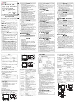
Setting the DIP Switches
Set DIP switches before installing and wiring readers. See
on page 7 for switch locations.
The following table provides switch settings for input types:
Note:
After changing DIP switch settings to modify input types,
be sure to reboot the IPSDC.
Switches SW4—SW7 are right-angle, momentary-contact push
buttons described in the following table and shown in
Note:
The reader board address is internally set to Address 1.
Connecting the Readers and Inputs
Use
on page 7 to wire the readers and inputs. Refer to
the reader documentation for wiring instructions.
Note the following details:
•
IPSDCs do not support the following TruPortal features:
Buzzer actions initiated by action triggers, auxiliary inputs/
outputs, and reader tamper inputs.
•
The reader DI port (J2) has two digital inputs which are used
for door status devices (door contacts and exit request input).
The inputs can be configured as supervised or non-
supervised. Inputs configured as supervised digital inputs
require End-of-Line (EOL) resistors.
•
The reader interface has built-in pull-up resistors to
accommodate cable lengths over 500 feet (152.4 meters). No
external pull-up resistors are required for the reader interface.
Note:
A TruPortal IPSDC Power Requirement Wattage
Calculator is included on the product disc in the
\Documentation\en-US folder for use in determining
peripheral loads.
Switch
Purpose
SW1 – Select Custom
Wiegand Card Format
[1]
1. Use the
System Administration > Card Formats
page
in the TruPortal User Interface to configure Wiegand
card formats.
Set SW1-1 to OFF and set SW1-2 thru
SW1-4 to ON.
SW2
Set all four DIP switches to OFF
SW1-5 and SW1-6
SW1-7
SW1-8
Supervised DI/REX 1,
4-State
N/A
ON
N/A
Supervised DI/REX 1,
2-State (default)
N/A
OFF
N/A
Switch
Purpose
SW4 – Boot Mode
Manually enables the ICT. See the
TruPortal
Software User Guide
for details.
SW5 – Hardware Reset
Reboots the IPSDC. Use this switch only if
performing a controlled manual shutdown, as
instructed by Technical Support.
SW6 – Shutdown Request
See
SW7 – Restore Defaults
Press SW7 for a minimum of five (5) seconds,
then release to return the configuration to factory
default settings:
Primary Connection Type:
Ethernet
IP Address:
192.168.6.6
Subnet Mask:
255.255.255.0
Gateway:
192.168.6.1
Table 1: Maximum Peripheral Loads
Reader/Strike
PoE
Auxiliary Power Supply
Voltage (DC)
12
24
12
24
Total watts available
8
10
12
20
Table 2: Device Current
Device
Operating
Voltage
Average
Measured
Current (mA)
Watts
T-100 reader
12
55
.66
T-200 reader
12
55
.66
T-500 reader
12
95
1.14
T-520 reader
12
105
1.26
T-525 reader
12
140
1.68
Securitron M62 Magnalock
strike
[1]
1. When using magnetic strikes with auto-voltage select, addi-
tional power allowances must be considered due to auto-
voltage circuitry operation.
12
240
2.88
Securitron M62 Magnalock
strike
[1]
24
140
3.36
HES, Inc 5000-12/24D strike
12
230
2.76
HES, Inc 5000-12/24D strike
24
115
2.76
Rutherford 4114x05x32D strike
12
190
2.28
Von Duprin 5100 3FP695
12 VDC
12
290
4.68
Von Duprin 5100 3FP695
24 VDC
24
195
4.68
RCR-REX
12
28
0.34
RCR-REX
24
17
0.41