


5
TruPortal IP-based Single Door Controller Quick Reference
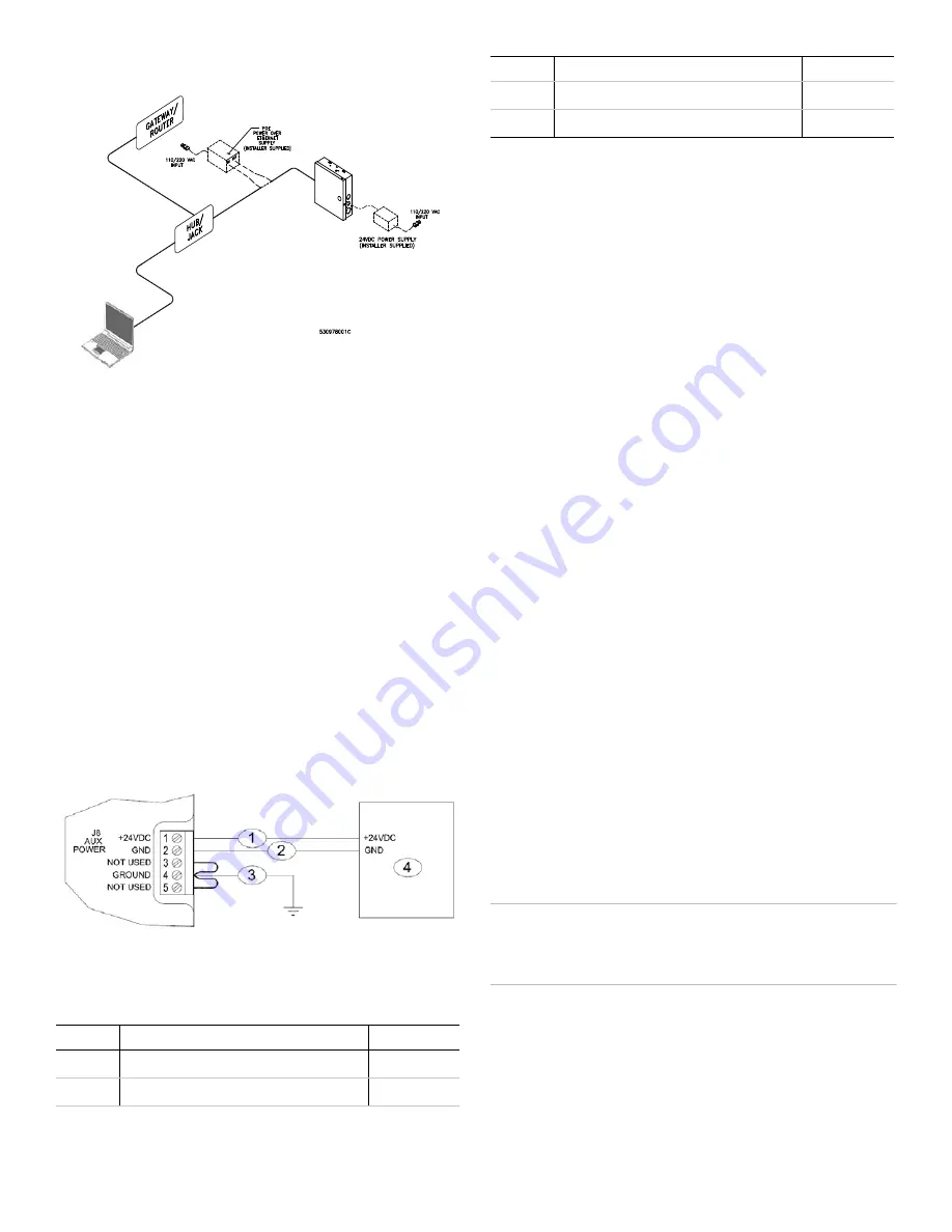
Figure 7: Connecting Through Network Hub Using PoE or Auxiliary Supply
Using an Auxiliary Power Supply
The IPSDC requires a 24 VDC nominal, 1 amp power supply with
battery backup. The IPSDC, readers, and other devices should be
referenced to the same ground.
For UL-listed installations, the auxiliary power supply must be an
approved UL294 power-limited supply, such as the Altronix Corp.
Model AL176ULX power supply. For UL of Canada (ULC)
installations, the auxiliary power supply must be listed to S319 or
S318.
1.
Mount the power supply near the IPSDC enclosure.
2.
Run the wire through the knockout hole to connector J8 (see
•
Pin 1 = +24 VDC
•
Pin 2 = – Ground (24 VDC return)
Note:
If the polarity is reversed, the fuse blows to prevent
damage. If the fuse blows, it automatically resets within
approximately five (5) seconds.
Figure 8: Auxiliary Power Supply Wiring
Note:
For UL-listed installations, Pin 3 is used for AC Power
Fail notifications; Pin 5 is used for Low Battery
notifications.
Configuring the IPSDC
After an IPSDC is installed, follow the instructions in the
TruPortal
Software User Guide
to use the browser-based Integrated
Configuration Tool (ICT) to:
•
Configure the IPSDC to recognize the IP address of the
System Controller (TP-SYS).
•
Change the IP address of the IPSDC.
Following is an overview of that procedure; see the
TruPortal
Software User Guide
or online help for details.
1.
Configure a local client workstation for static IP address
192.168.6.1 or a similar valid IP address (e.g., 192.168.6.
x
where
x
is any number between 1 and 254 except 6).
2.
Make sure that the PC is not blocked from connecting to IP
address 192.168.6.6. (If the workstation normally connects to
the Internet via a proxy, the proxy settings in the browser may
need to be adjusted.)
3.
Open an Internet browser and go to http://192.168.6.6, the
default address of the IPSDC.
4.
Type the
User ID
and
Password
for the ICT.
The default values are
install
and
install
.
5.
On the
Controller Parameters > Primary Network
page,
configure the correct IP address for this IPSDC. A static IP
address is highly recommended. Make a note of the address
for your records. Click
Save
and then
Apply
.
6.
On the
Controller Parameters > Panel Configuration
page,
type the IP address of the System Controller. Click
Save
and
then
Apply
.
7.
Click
Restart Application
to commit the changes.
After a few minutes, the IPSDC will be accessible via the new
IP address and can be detected by the System Controller
when the [Scan for Hardware Changes] button is clicked in
the TruPortal User Interface.
8.
Repeat the procedure for each IPSDC.
Safe Shutdown Procedure
The following procedure can be performed in maintenance mode
or normal operation mode to turn off the IPSDC.
WARNING:
Do not reset or restart the IPSDC in the middle of a
firmware update or the IPSDC will become
nonfunctional. Refer to the
TruPortal Software User
Guide
for more information about firmware updates.
1.
Press SW6 and hold the button for three seconds until LEDs
D14 through D21 turn on and stay on. (See
locations of reset switches and LEDs.)
2.
Wait for about five seconds.
3.
Remove power to the IPSDC or push SW5 to reset the
IPSDC.
Callout
Description
Wire Color
1
+24 VDC from auxiliary power supply
Red
2
Ground (0V) from auxiliary power supply
Black
3
Factory-wired chassis ground. Do not remove.
Green
4
+24 VDC auxiliary power supply
Callout
Description
Wire Color


