background image

Network Video Recorder 
User Manual 

Quick Navigation 


64 


      Issue V4.6 (2021-05-12) 


Snapshot in real time video, put the cursor on picture such as 

, you can add it to face 

library, or face search. The cursor on area 6 and the pictures is not update, move the mouse so 

that the pictures can be shown in time. 


6.4.2.2


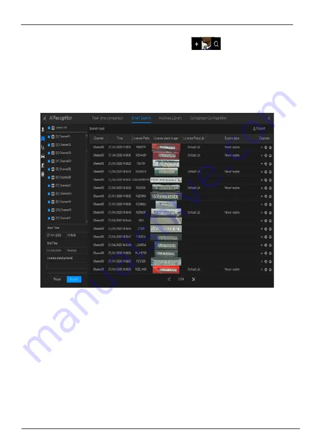
Vehicle License Plate Search 

Figure 6-27


Vehicle License Plate search 


Step 1


Choose vehicle License Plate at smart search interface. 

Step 2


Tick the vehicle license plate recognition camera channels, set the start time and end time. 

Step 3


Input the license plate optionally. 

Step 4


Click “Search” to search the snapshot of license plate. 

Step 5


The result will show at the page, click “+” add to library. 

Step 6


Click “Playback” to view the recording video, click “Backup” to backup the video. 

Step 7


Click “Export” to export the result. 


Summary of Contents for INTIPCK825TH

Page 1: ...Network Video Recorder NVR User Manual Issue V4 6 Date 2021 05 12 ...

Page 2: ......

Page 3: ...emails telephones and GPS In the process of using the product you need to comply with the privacy protection laws and regulations of your region or country to protect the legitimate rights and interests of others For example provide clear and visible signs inform the relevant rights holders of the existence of video surveillance areas and provide corresponding contact information About This Docume...

Page 4: ...ansmission The information transmission between the front end device and the recording device is fully encrypted 4 Enable IP filtering After IP filtering is enabled only devices with the specified IP address can access the system 5 Change the ONVIF password Some old versions of the IP camera firmware after the system s master password is changed the ONVIF password will not be automatically changed...

Page 5: ...ack on your network 12 Check logs If you want to know if your device is secure you can check the logs to find some unusual access operations The device log will tell you which IP address you have tried to log in or what the user has done Physically protect your device For the safety of your device we strongly recommend that you physically protect your device from unauthorized boring operations We ...

Page 6: ...4 spilt screens of automatic adjusting main stream or sub stream Add private protocol access Support multi screen playback Add the schedule recording function by channel setting Increase the allocation of permissions by channel V 4 2 Add boot wizard Add toolbar Add manual recording and timely playback Add multiple clicks to enlarge Add user lockout Remove the upper right corner to display the alar...

Page 7: ...video dual authentication and boot wizard configuration function Add alarm log Add interval update profile 6 V 4 2 1 Add the NTP synchronization interval and add the manual NTP synchronization interval Add access to thermal imaging cameras and display IPC product models Remove auto hide Add the patrol route and line sweep function Add upgrade IPC restart IPC restore factory IPC Increase the select...

Page 8: ...ion Add P2P server 8 V 4 3 Add pattern unlock Add mailbox reset password Increase the secure question reset password Add 1 7 split screen Add channel information display Add 3D ball machine Remove the video type switch from the scene Add RAID Add S M A R T Add formatting fat32 and NTFS Support event video quick download backup Add event video backup Add the full screen of the bomb and send the scr...

Page 9: ...mometer Add temperature schedule linkage Add smart functions Add smart tracking Add microphone Add the synchronization camera time Add personnel count 202005 11 V4 5 1 Add mask detection configuration Increase personnel counting configuration Optimize the camera to manually add camera channels Optimize record schedule Optimized auto sequence Increase NAT port settings Increase network packet captu...

Page 10: ... phone number and refine the backup authority Add multiple layouts to auto sequence System log is saved to flash and hard disk Symbol Conventions The symbols may be found in this document which are defined as follows Symbol Description Alerts you to a high risk hazard that could if not avoided Alerts you to a medium or low risk hazard that could if not avoided result in moderate or minor injury Al...

Page 11: ...r of explosion Be sure to use the battery as required otherwise there is a danger of the battery catching fire exploding or burning Only use the same model of battery when replacing the battery Be sure to dispose of the used battery as the instruction of battery Be sure to use the power adapter that meets standard with the device otherwise the personal injury or equipment damage caused by the user...

Page 12: ...rements ix Power Requirement ix Important Statement ix Contents x 1 Preface 1 1 1 Product Description 1 1 2 Product Features 1 1 2 1 Cloud Upgrade 1 1 2 2 Real time Monitoring 2 1 2 3 Playback 2 1 2 4 User Management 2 1 2 5 Storage Funtion 2 1 2 6 Alarm Function 3 1 2 7 Network Monitoring 3 1 2 8 Split Screen 3 1 2 9 Recording Function 3 1 2 10 Backup Function 4 1 2 11 External Device Control 4 1...

Page 13: ...e or Two Hard disks 18 3 3 2 Install Four Hard disks 19 3 3 3 Install Eight Hard disks 20 4 Basic Operations 22 4 1 Power on the Device 22 4 2 Activation 23 4 3 Power off the Device 28 4 4 Login to the System 28 5 Wizard 31 6 Quick Navigation 40 6 1 Alarm message 44 6 2 Real Time Video Bar 45 6 3 Playback 48 6 3 1 Time Search 51 6 3 2 Picture Grid 52 6 3 3 Event Recording 54 6 3 4 Backup 56 6 4 AI...

Page 14: ... Plate Library 70 6 4 4 Comparison Configuration 71 6 4 4 1 Face Comparison 72 6 4 4 2 License Comparison 73 6 4 4 3 Temperature Comparison 75 6 4 4 4 Mask Detection Configuration 77 6 4 4 5 Personnel Count Configuration 79 6 5 Attendance 81 6 5 1 Attendance Data 81 6 5 2 Attendance Management 82 6 6 Thermal Temperature 85 6 6 1 Temperature Parameters 86 6 6 2 Temperature Area 90 6 6 3 Schedule Li...

Page 15: ...an Thermometer 112 7 1 8 1 Parameter Configuration 112 7 1 8 2 Thermal Mapping 118 7 1 8 3 Thermal Calibration 119 7 1 9 Smart 120 7 1 9 1 AI Multiobject 121 7 1 9 2 License Plate Recognition 123 7 1 9 3 Face Detection 125 7 1 10 Intelligent Tracking 127 7 2 Record Setting 130 7 2 1 Record Schedule 130 7 2 2 Disk 131 7 2 3 RAID 133 7 2 4 Storage Mode 134 7 2 5 S M A R T 136 7 2 5 1 S M A R T 136 7...

Page 16: ...ut 157 7 3 7 1 Alarm Out 157 7 3 7 2 Camera Alarm out 157 7 4 Network Management 159 7 4 1 Network 160 7 4 1 1 IP 160 7 4 1 2 Port 161 7 4 1 3 IPv4CCTV 161 7 4 1 4 POE 162 7 4 1 5 WiFi Parameter 163 7 4 1 6 WiFi Network 164 7 4 2 802 1 X 165 7 4 3 DDNS 166 7 4 4 Port Mapping 167 7 4 4 1 Port Mapping 167 7 4 4 2 NAT Port 168 7 4 5 E mail 169 7 4 6 P2P 171 7 4 7 IP Filter 172 7 4 8 SNMP 174 7 4 9 3G...

Page 17: ... 192 7 5 3 3 Security Code 193 7 5 3 1 Password 193 7 5 3 2 Pattern Unlock 194 7 5 3 3 Secure Email 195 7 5 3 4 Secure Question 196 7 5 4 Layout 197 7 5 5 Auxliary Screen 201 7 5 6 Logs 202 7 5 6 1 System Log 202 7 5 6 2 Event Log 203 7 5 7 Maintenance 204 7 5 8 Auto Reboot 207 8 WEB Quick Start 208 8 1 Activation 208 8 2 Login and Logout 210 8 3 Browsing Videos 214 8 3 1 Browsing Real Time Videos...

Page 18: ...232 8 7 1 3 Vehicle and Full Body 233 8 7 1 4 Real Time Body Temperature Filter 234 8 7 2 Smart Search 235 8 7 2 1 Human Face Search 236 8 7 2 2 Vehicle License Plate Search 237 8 7 2 3 Full Body Search 238 8 7 2 4 Vehicle Search 239 8 7 2 5 Body Temperature Search 240 8 7 2 6 Personnel Count 240 8 7 3 Archives Library 241 8 7 3 1 Face Library 241 8 7 3 2 License Plate Library 242 8 7 4 Comparison...

Page 19: ...D 261 9 2 4 S M A R T 263 9 2 5 Disk Calculation 264 9 2 6 Storage Mode 265 9 2 7 Cloud Storage 266 9 3 Alarm 266 9 3 1 General 267 9 3 1 1 General 267 9 3 1 2 IO Control Push 267 9 3 2 Motion Detection 268 9 3 3 Video Loss 270 9 3 4 Intelligent Analysis 271 9 3 5 Alarm In 272 9 3 6 Abnormal Alarm 273 9 3 7 Alarm out 274 9 4 Network 275 9 4 1 Network 275 9 4 2 DDNS 277 9 4 3 E mail 278 9 4 4 Port ...

Page 20: ...us 288 9 5 System 289 9 5 1 Device Information 289 9 5 2 General 292 9 5 3 User Account 296 9 5 3 1 Add User 296 9 5 3 2 Adv Setting 298 9 5 4 Secutiy Code 298 9 5 5 Security Center 299 9 5 5 1 Password 299 9 5 5 2 Secure Email 300 9 5 5 3 Secure Question 300 9 5 6 Logs 301 9 5 6 1 Logs 301 9 5 6 2 Event 301 9 5 7 Maintenance 302 9 5 8 Auto Reboot 303 9 6 Local 304 10 Disk Compatibility 306 ...

Page 21: ...is combined with other front end devices such as network cameras network video server networks and professional video surveillance systems to form a powerful security monitoring network In the networked deployment system of this product the central point and the monitoring point need only one network cable to connect It is not necessary to set up visual and audio lines to the monitoring point and ...

Page 22: ...me when the event occurred can be displayed during playback of the recording You can select any area of the screen for partial magnification 1 2 4 User Management Each user group has a rights management set which can be selected autonomously The total rights set is a subset and the user rights in the group cannot exceed the rights management set of the user group 1 2 5 Storage Funtion According to...

Page 23: ... The audio and video data is transmitted using protocols such as HTTP Hyper Text Transfer Protocol TCP Transmission Control Protocol UDF User Datagram Protocol MULTICAST RTP Real time Transport Protocol and RTCP Real Time Streaming Protocol Use SNMP Simple Network Management Protocol for some alarm data or information Support WEB mode access system applied to WAN LAN environment 1 2 8 Split Screen...

Page 24: ...nsparent data transmission of multiple interfaces such as RS232 RS485 1 2 12 Accessibility Supports video NTSL Nation Television Standards Committee system and PAL Phase Alteration Line system Supports system resource information and real time display of running status Supports for logging recording Supports local GUI Graphical User Interface output and quick menu operation via mouse Supports play...

Page 25: ... Description PWR When the NVR is operating the PWR indicator is steady on When the NVR is shut down the PWR indicator is turned off HDD Hard disk status indicator This indicator flashes when data is transmitted POE PoE network status indicator This indicator flashes when data is transmitted KB MOUSE Only supports connected to an USB mouse BACKUP Only supports connected to U disk Figure 2 2 One dis...

Page 26: ...hen data is transmitted Only supports connected to an USB mouse Figure 2 3 Eight disk model PW R H D D Table 2 3 Front panel function Port Description PWR When the NVR is operating the PWR indicator is steady on When the NVR is shut down the PWR indicator is turned off HDD Hard disk status indicator This indicator flashes when data is transmitted Only supports connected to an USB mouse Figure 2 4 ...

Page 27: ...ected to an USB mouse 2 2 Back Panel Figure 2 5 One disk 4 POE DC 48 V USB H D OUT VG A RE SET L A N POE 1 2 4 3 Figure 2 6 Two disks 8 POE AU DIO ALA RMI O H D M I Table 2 5 Real panel function Port Description POE POE network interfaces LAN RJ 45 10 100 1000 Mbps adaptive Ethernet interface AUDIO OUT AUDIO IN Audio output Audio input VGA Video output interface HDMI Alarm I O Alarm input Alarm ou...

Page 28: ...DIO IN Audio output Audio input VGA Video output interface HDMI USB 3 0 Only supports connected to 3 0 U disk Alarm I O Alarm input Alarm output GND DC48V Connected to an external power adapter Figure 2 8 Four disks eight disks eSATA 1 2 3 4 5 6 7 8 9 1 0 11 12 13 14 15 16 ALA R M I N A LAR M I N C O M G N D 48 5 A B 4B4A3B 3A 2B2A1B 1A 2 1 1 4K R S 232 2 Table 2 7 Real panel function Port Descrip...

Page 29: ...tch Safe ground screw of the device AC 110V 220V power input interface Figure 2 9 Four disks 16 POE eSATA Table 2 8 Real panel function Port Description POE port POE network interfaces Alarm input and alarm output RS485 LINE OUT LINE IN Audio output Audio input LAN RJ 45 10 100 1000 Mbps adaptive Ethernet interface VGA Video output interface HDMI RS232 Standard RS232 serial communication interface...

Page 30: ...V 220V power input interface Figure 2 10 WiFi model H D O U T VG A WAN D C 12V Table 2 9 Real panel function Port Description WAN RJ 45 10 100 1000 Mbps adaptive Ethernet interface VGA Video output interface DC 12V Connected to an external power adapter Safe ground screw of the device ...

Page 31: ...Product Structure Network Video Recorder User Manual Issue V4 6 2021 05 12 11 ...

Page 32: ...Network Video Recorder User Manual Product Structure 12 Issue V4 6 2021 05 12 ...

Page 33: ...ing the NVR Please read the user manual carefully before using this product The NVR is a complex system based device To avoid misoperations and malfunctions caused by environmental factors and human factors during installation commission and application note the following points when installing and using this product ...

Page 34: ... user manual is intended for persons who operate and use the NVR The information in this user manual applies to the full series NVR NVR as an example for description Read this user manual carefully before using the NVR and follow the methods described in this manual when using the NVR If you have any doubts when using the NVR contact your product seller In the case of product upgrade the informati...

Page 35: ... installation The NVR is not configured with any hard disk upon delivery Install one or more hard disks when using the NVR for the first time The NVR identifies hard disk capacity automatically and supports mainstream hard disk models User should use good brands of hard disk so that the NVR can operate stably and reliably please refer to chapter 10 Disk Compatibility Other precautions Clean the NV...

Page 36: ...work Video Recorder User Manual Install device 16 Issue V4 6 2021 05 12 3 Install device 3 1 Process Start Unpacking inspection Install hard disk Connect cable Configure and enter interface Boot device End ...

Page 37: ...ct our sales technicians Table 3 1 Unpacking inspection No Item Check content 1 Overall packaging Appearance Is there any obvious damage Package Is there accidental impact Accessories Is it complete 2 Label Label of device Is the equipment model consistent with the order contract Whether the label is torn Do not tear or discard otherwise warranty service is not guaranteed When you call the company...

Page 38: ...d disk capacity according to the recording requirements 3 3 1 Install One or Two Hard disks Step 1 Remove the screws for fixing the upper cover and take down the cover Step 2 Take out the screws and silicone cushion route the screws through the silicone cushion and install it to the screw holes as show in Figure 3 1 Figure 3 1 Installing the hard disk screws Step 3 Route the screws through the hol...

Page 39: ...Insert the hard disk data cable and power cable then put on the upper cover and fasten the fixing screws 3 3 2 Install Four Hard disks Step 1 Remove the screws for fixing the upper cover and take down the cover Step 2 Put the hard disk under the hard disk bracket hold the hard disk with one hand and aim the hard disk hole at the bracket hole then fix the screws for hard disk install the hard disk ...

Page 40: ... the upper cover and take down the cover Step 2 Unscrew the screws on both sides and the upside of the upper bracket respectively lift the upper bracket as shown Figure 3 5 Unscrew the screws lift the upper bracket upper bracket screws Step 3 Put the hard disk under the lower bracket hold the hard disk with one hand and aim the hard disk hole at the bracket hole then fix the screws for hard disk a...

Page 41: ...der Install device User Manual Issue V4 6 2021 05 12 21 Figure 3 6 Unscrew the screws lift the upper bracket Step 5 Insert the hard disk data cable and power cable then put on the upper cover and fasten the fixing screws ...

Page 42: ... interface HDMI or video graphics array VGA port of the NVR before power on In some environments abnormal power supply may cause the failure of the NVR to work properly and even damage the NVR in severe cases It is recommended to use a regulated power supply to power the NVR in such environments After the NVR is connected to a power supply the power indicator is steadily on Start the NVR The real ...

Page 43: ...the possible causes are as follows The hard disk is new and is not formatted Login to the system and format the hard disk The hard disk is formatted but the file system is inconsistent with the file system supported by the NVR Format the hard disk The hard disk is damaged 4 2 Activation When the user login the device at first time or reset the NVR you need to activate the device and set login and ...

Page 44: ...per administrator Password Valid password range 6 32 characters At least 2 kinds of numbers lower case upper case or special characters contained Only these special characters are supported Channel default password limit is not empty Confirm password Channel password The NVR channel connection password is the camera login password User can set the pattern unlock to login the device as shown in Fig...

Page 45: ...nlocked the system defaults to the pattern unlock login If the pattern unlock is not set you will need to input the password to login If you don t need to set the pattern to unlock click Skip this step Set the Email to receive the verification code if user forget the initial password to create new password as shown in Figure 4 4 ...

Page 46: ...ceive the verification and reset the password If the email address is not set you can reply to the secure question or send the QR code to the seller to give the temporary password to login to the device If you don t need to set the email click Skip this step Set the secure question if user forgot the password can through the secure questions to create new password to login the device ...

Page 47: ...an be set Your favorite animal Company name of your first job The name of the first boy girl you like The worst security question you have ever seen The most funning worst design you have ever seen Your favorite team Your favorite city The three question options cannot be set to the same issue The answer requires a minimum of four characters and a maximum of 32 characters If you do not want to set...

Page 48: ...e setting page is displaying click Shutdown to power off the NVR If there is a power switch on the rear panel of the NVR you can RPM off the power switch to disconnect the NVR from the power supply 4 4 Login to the System Step 1 Login to the device there are two modes to login if you set the pattern unlock as shown in Figure 4 6 Figure 4 6 Pattern unlock login page ...

Page 49: ...d incorrect more than 3 times please login again after 5 minutes You can also power off and power on to start on the device input the correct password to avoid waiting five minutes If user forget password click Forgot password User can choose a way to create new password 1 Scan the QR code and send the QR code to your seller seller send the verification code to user and set new password to login 2...

Page 50: ...Network Video Recorder User Manual Basic Operations 30 Issue V4 6 2021 05 12 Figure 4 8 Modify default password End ...

Page 51: ...etwork Video Recorder Wizard User Manual Issue V4 6 2021 05 12 31 5 Wizard Login the NVR the wizard is showing on live video click Start Wizard the pop up window will show as Figure 5 1 Figure 5 1 Wizard ...

Page 52: ...ase refer to Table 5 1 Table 5 1 Network parameter Parameter Description Configuration DHCP Enable DHCP the device will obtain the IP address from the DHCP server Setting method Enable IP Address Set the IP of device when DHCP is disable Setting method Manual Subnet mask Set the subnet mask of device Setting method Manual Default value ...

Page 53: ...method Manual Default value 192 168 0 1 Alternate DNS Server N A Setting method Manual Default value 8 8 8 8 Enable Port Mapping Enable to set the ports of HTTP HTTPS RSTP Control Auto device to obtain Web port data port and client port Manual user set the port manually Setting method Choose type from drop down list Default value Auto Web Port N A Setting method When UPnP is manual you need to set...

Page 54: ...wn list Click to synchrony time from network Disable the NTP Sync set time manually Roll the mouse to choose year month and day when clicking the date Roll the mouse to choose hour minute and second when clicking the date Click Modify Time to save the time Step 3 Click Time Zone choose the current time zone from drop down list as shown in Figure 5 4 ...

Page 55: ...User Manual Issue V4 6 2021 05 12 35 Figure 5 4 Wizard of time zone Step 4 Click DST enable the DST set start and end time Select offset time from drop down list Step 5 Click to enter the adding camera wizard as shown in Figure 5 5 ...

Page 56: ...Video Recorder User Manual Wizard 36 Issue V4 6 2021 05 12 Figure 5 5 Wizard of adding camera The details of adding camera please refer to chapter 7 1 Step 6 Click to enter wizard of disk as shown in Figure 5 6 ...

Page 57: ...o Recorder Wizard User Manual Issue V4 6 2021 05 12 37 Figure 5 6 Wizard of disk You can view the general information of disk You can also format the disk Step 7 Click to enter wizard of P2P as shown in Figure 5 7 ...

Page 58: ... user can use mobile devices to manage the NVR by scanning the P2P ID if the mobile phone has loaded the InView Pro 4 search the APP at App Store or Google Play Step 9 Click to enter the wizard of resolution as shown in Figure 5 8 Choose resolution from drop down list the highest resolution is 3840 2160 ...

Page 59: ...izard User Manual Issue V4 6 2021 05 12 39 Figure 5 8 Wizard of resolution Step 10 Click to end the wizard tick the Not show this window next time wizard would not show at next time Reopen wizard at system user advance setting ...

Page 60: ... operation screen is displaying move the cursor to the down most position of the NVR screen The NVR floating menu bar is displaying Click in the left of NVR floating menu bar The quick home menu is showing The quick home menu provides Playback System and Power Shutdown Reboot and Logout as shown in Figure 6 1 ...

Page 61: ...1 Figure 6 1 Quick home menu In the middle of NVR floating menu bar the video tool bar provides video window switching auto SEQ volume playback and channel information as shown in Figure 6 2 Figure 6 2 Real time video toolbar The real time video toolbar is described as follows ...

Page 62: ...6 3 Add layout Input the layout name choose the dwell time choose the splitting format Choose one channel or many channels to add on screen Auto SEQ click icon the layout dwell on screen is enabled for how to set the dwell on please see chapter 7 5 4 Audio Click icon the audio setting screen is displaying which you can choose the channel and adjust the volume Channel information tick the channel o...

Page 63: ...uick toolbar is display on the right of NVR floating menu bar The main menu quick toolbar provides manual alarm alarm information clean alarm information and time as shown in Figure 6 4 Figure 6 4 Main menu quick toolbar Manual alarm click the icon user can set different channels choose alarm out the window shows in Figure 6 5 Figure 6 5 Manual alarm Alarm message click icon would show pop up mess...

Page 64: ...21 05 12 6 1 Alarm message Clean alarm click icon and clean the current alarm actions like voice and external alarm out Information click icon and the general information would show like network system channel disk and alarm as shown in Figure 6 6 Figure 6 6 Information ...

Page 65: ... playback Audio open or close the audio PTZ This function only is useful for speed dome cameras You can adjust every parameter as shown in Figure 6 7 Figure 6 7 PTZ adjust screen User adjust direction of camera At this part user can set Advanced Scan and Tour settings 3D this function only can be used for high speed dome camera Click the icon to enter the camera live video screen use the mouse to ...

Page 66: ...t the zooming Image click the icon as shown in Figure 6 8 Select scene and drag cursor to adjust value of brightness sharpness contrast and saturation Figure 6 8 Camera picture parameter Two way audio The NVR and camera can talk to each other snapshot panorama if the USB disk is plugging in the NVR fisheye click to switch the fisheye modes as shown in Figure 6 9 ...

Page 67: ...ation User Manual Issue V4 6 2021 05 12 47 Figure 6 9 Fisheye Modify device parameters remote channel is based on cameras human body temperature have two remote channels fisheye cameras have four remote channels as shown in Figure 6 10 ...

Page 68: ...on 48 Issue V4 6 2021 05 12 Figure 6 10 Modify device parameter 6 3 Playback Playback refers to playing back a video fixed point playback playback the search type Click in the quick navigation bar to access the playback screen as shown in Figure 6 11 ...

Page 69: ...yback screen The toolbar at the bottom of the playback screen is described as follows Layout Reversed pause play stop 30s backward 30s forward Triple speed it supports up to 32 times to playback Click the Number can choose the speed quickly Zoom Roll the roller of mouse can also zoom in or out ...

Page 70: ...e 6 12 Click OK to save This function is available after a USB disk is plugging in the device Figure 6 12 Select directory Batch backup click the icon to backup multi channels as shown in Figure 6 13 Choose the folder to save select the stream information from drop down list set the start time and end time select the channels Click OK to backup the backup videos are marked by watermark you can vie...

Page 71: ... 2021 05 12 51 Figure 6 13 Batch backup Type of time bar recording video can show 6 3 1 Time Search Search refers to searching for a video by date and time Operation Description Click in the quick navigation bar to access the search screen as shown in Figure 6 14 ...

Page 72: ...deo view of the selected camera is displaying in the play window Step 2 Select a date in the calendar on the light down side of the search screen Step 3 Choose record type and search the video quickly Step 4 Choose proper button to adjust video End 6 3 2 Picture Grid Picture grid refers to evenly dividing the video of a channel by time range and searching for a video based on thumbnails divided by...

Page 73: ... camera list on the left side of the picture grid screen Videos shot by the camera in the earliest time range on the current day are displayed as thumbnails in the window on the right side Step 2 Select a day from calendar Step 3 A day are dividend to 12 grids two hours is one grid Click the image to change the interval Step 4 Select a required thumbnail double click it or right click it and choos...

Page 74: ...k Navigation 54 Issue V4 6 2021 05 12 Step 5 Click to replay the gird individually Figure 6 16 Replay End 6 3 3 Event Recording Click on the quick navigation bar choose Event at title to access the alarm event screen as shown in Figure 6 17 ...

Page 75: ...t on the left Step 2 Set start and end time Step 3 Tick the alarm type such as alarm in camera alarm in motion alarm video loss intelligent analysis and abnormal alarm Step 4 Click to query the event the result would show at window Step 5 Double click to play video about event It will play recording video play the recording video backup the recording video ...

Page 76: ...bad register stranger registered license plate over temperature low temperature abnormal temperature threshold warning threshold alarm temperature difference warning temperature difference alarm temperature section alarm face temperature wear mask no mask personnel count threshold alarm personnel count threshold alarm IPC Abnormal alarm includes disk error IP conflict network disconnected User can...

Page 77: ...guration The all snapshots support to add to the libraries according the real needs 6 4 1 Real Time Comparison Real time comparison can compare human faces vehicle license plate and AI include riding vehicle full body 6 4 1 1 Human Face At real time comparison interface click the to enter the human face comparison interface choose the cameras with face recognition function to play live video the s...

Page 78: ...d it to face library or face search The cursor on area 6 and the pictures are not update move the mouse so that the pictures can be shown in time 6 4 1 2 Vehicle License Plate At real time comparison interface click the to enter the vehicle license plate comparison interface choose the cameras with license plate recognition function to play live video the snapshot of camera will be compared with l...

Page 79: ...e library immediately 6 4 1 3 Vehicle and Full Body At real time comparison interface click the to enter the vehicle license plate comparison interface choose the AI recognition cameras to play live video the snapshot of camera will compare in libraries the snapshot to vehicle and full body will show at the bottom of page the result shows as in Figure 6 21 ...

Page 80: ...4 Real time Body Temperature Filter At AI recognition click to enter the real time body temperature filter user can choose human body temperature cameras to show it will show the temperature recording and over temperature snapshots Click full screen the channel list and snapshots statistics will be hidden ...

Page 81: ...eo Recorder Quick Navigation User Manual Issue V4 6 2021 05 12 61 Figure 6 22 Real time body temperature filter Figure 6 23 Full screen If user enable the mask detection the results will show wear mask or no mask ...

Page 82: ...1 Choose human face search at smart search interface Step 2 Tick the face recognition camera channels set the start and end time Step 3 Choose the condition by picture or by feature the picture can choose from the file folder Step 4 Click Search to search the snapshot of human face Step 5 The result will show at the middle of page click the picture and the detail information show at the top right ...

Page 83: ... User Manual Issue V4 6 2021 05 12 63 Figure 6 25 Back up Step 8 Click Export to export the result choose export type pictures or videos Figure 6 26 Export Play video of snapshot it will play a 30 seconds video before and after the snapshot ...

Page 84: ...e License Plate Search Figure 6 27 Vehicle License Plate search Step 1 Choose vehicle License Plate at smart search interface Step 2 Tick the vehicle license plate recognition camera channels set the start time and end time Step 3 Input the license plate optionally Step 4 Click Search to search the snapshot of license plate Step 5 The result will show at the page click add to library Step 6 Click ...

Page 85: ...camera channels set the start time and end time Step 3 Set the gender click cycling or no cycling Step 4 Click Search to search the snapshot of human face Step 5 The result will show at the middle of page click the picture and the detail information show at the top right of page Step 6 Click play button of video to play the recording of snapshot click backup to backup the video Step 7 Click Export...

Page 86: ...gnition camera channels set the start time and end time Step 3 Tick the color Step 4 Click Search to search the snapshot of human face Step 5 The result will be showed at the middle of page click the picture and the detail information show at the top right of page Step 6 Click play button of video to play the recording of snapshot click backup to backup the video Step 7 Click Export to export the ...

Page 87: ... Body temperature search Step 1 Choose body temperature search at smart search interface Step 2 Tick the AI recognition camera channels set the start time and end time Step 3 Choose the person type temperature type input ID optionally Step 4 Click Search to search the temperature Step 5 Click Export to export the result ...

Page 88: ...rch interface Step 2 Tick the AI recognition camera channels set statistical type and date Step 3 Click Search to search the snapshot of human face Step 4 Click to view the data by different manners 6 4 3 Archives Library At archives library user can add or edit the face library license plate library The license plate libraries can be import to and export from IP cameras ...

Page 89: ...ary Figure 6 32 Face library Click to add face library Click Add to add person enroll Tick the person click Delete to delete the person Click Import to add the person batch Click Export to export the all person in library Click Filter to filter the all persons in library as shown in Figure 6 33 ...

Page 90: ...edit or delete the chosen person 6 4 3 2 License Plate Library At license plate library interface user can add delete operate the library It supports the white list and black list according the libraries to export and import the library to IP cameras Figure 6 34 License plate library Click to add license plate library ...

Page 91: ...add the license plate batch Click Export to export the all license plate library Click operate icon to edit or delete the chosen license plate Click Import from Camera to select license plate library to channel Click Export to Camera to add license plate number to camera 6 4 4 Comparison Configuration The comparison function is only for AI cameras please refer to actual cameras NOTE ...

Page 92: ... of human face license plate temperature mask detection configuration personnel count configuration 6 4 4 1 Face Comparison At face comparison interface user can set different channels strategy such as similarity display comparison result face library enable alarming event action arming time as shown in Figure 6 35 Figure 6 35 Face comparison ...

Page 93: ...021 05 12 73 Figure 6 36 Strategy 6 4 4 2 License Comparison At license plate interface use can set strategies of different channels of license plate recognition cameras such as register and unregister enable alarming event action arming time as shown in Figure 6 37 ...

Page 94: ...Network Video Recorder User Manual Quick Navigation 74 Issue V4 6 2021 05 12 Figure 6 37 License comparison Figure 6 38 Strategy ...

Page 95: ...mperature comparison At temperature comparison interface user can set low temperature threshold high temperature threshold normal temperature Abnormal temperature measurement alarm when it is turned on the temperature below the low threshold and above the high temperature threshold will generate abnormal temperature alarm When it is turned off body temperatures below the low threshold and above th...

Page 96: ...e V4 6 2021 05 12 Figure 6 40 Schedule linkage Enable alarm set the schedule linkage it will send alarm information if the temperature is higher than low threshold and lower the normal temperature or higher than normal temperature and lower than high threshold ...

Page 97: ...vigation User Manual Issue V4 6 2021 05 12 77 6 4 4 4 Mask Detection Configuration Figure 6 41 Mask detection configuration Enable mask detection choose the mode no mask or wear mask Set the confidence degree the default value is 90 ...

Page 98: ...anual Quick Navigation 78 Issue V4 6 2021 05 12 Figure 6 42 Schedule linkage Enable the alarm the real time comparison can show if one the wear mask or not Choose event actions and set the schedule Click Apply to save the settings ...

Page 99: ...liary screen you need to start the auxiliary screen in System Auxiliary Screen before displaying Select the counting clear interval never 10 minutes half an hour 1 hour 12 hours 1 day Set correction value Configure the calibration value to start the manual calibration of the personnel count value Alarm threshold when the number of people counts reaches the threshold an alarm is activated Alarm int...

Page 100: ...Network Video Recorder User Manual Quick Navigation 80 Issue V4 6 2021 05 12 Figure 6 44 Schedule linkage Set schedule linkage action to alarm ...

Page 101: ...o enter attendance data interface as shown in Figure 6 45 Figure 6 45 Attendance data Operation Steps Step 1 Tick the attendance library Step 2 Choose time mode such as today this week this month and custom time Step 3 Choose search type such as attendance summary and attendance details Step 4 Click search the result will show in interface Step 5 Click Export to export the query result ...

Page 102: ...d check point as shown in Figure 6 46 Figure 6 46 Attendance rule settings Operation Steps Step 1 Set start work time and end work time Step 2 Tick the workday Step 3 Set valid time of check in and check out Step 4 Click Save to save the setting Attendance library Step 1 Click Attendance Library to add library the attendance library can call the face database directly ...

Page 103: ...Tick the library and click Add to add to attendance library If you want to modify the library Step 3 click to enter the face database management to modify parameter Step 4 Click Save to save the setting Attendance check point settings Step 1 Click Attendance check point settings to set point as shown in Figure 6 48 ...

Page 104: ...Network Video Recorder User Manual Quick Navigation 84 Issue V4 6 2021 05 12 Figure 6 48 Attendance check point setting s Step 2 Click to edit check point setting as shown in Figure 6 49 ...

Page 105: ...Enable the function set similarity and tick the library all face detection cameras can be set the check points Step 4 Click OK to save the setting End 6 6 Thermal Temperature The thermal temperature function is only carried by some devices If the current device does not have the function please ignore it NOTE ...

Page 106: ...re correctional coefficient and area temperature display mode Operation Procedure Step 1 Choose Thermal Temperature Parameters The Temperature Parameters page is displayed as shown in Figure 6 50 Figure 6 50 Temperature Parameters interface Step 2 Set the parameters according to Table 6 1 Table 6 1 Temperature parameters Parameter Description Setting Open Temperature Measure Enable temperature mea...

Page 107: ...ject temperature and actual temperature For example 1 The measured object temperature is 30 and actual temperature is 37 so the correction coefficient should be 7 2 The measured object temperature is 37 and actual temperature is 30 so the correction coefficient should be 7 Setting method Enter a value manually Default value 0 00 Area Temperature Display Mode The display position of temperature inf...

Page 108: ...od Select a value from the drop down list box Default value Highest Temperature Measure Mode There are two types measure modes Setting method Select a value from the drop down list box Default value General Display Alarm Area N A Setting method Enable or disable Default value disable Area Alarm Interval N A Setting method Enter a value manually ranges from 1 to 1800 Default value 10 ...

Page 109: ...m Setting method Select a value from the drop down list box Default value Auto Greater Prominent Enable that the image will show the setting color if the temperature is higher than set value Setting method Enter a value manually Choose one color to show Section Prominent Enable that the image will show the setting color if the temperature is between minimum and maximum temperature Setting method E...

Page 110: ...nually Choose one color to show Step 3 Click Copy to copy the same settings to others thermal cameras Step 4 Click Apply Step 5 The message Apply success is displayed the system saves the settings End 6 6 2 Temperature Area Operation Procedure Step 1 Choose Thermal Temperature Area The Temperature Area page is displayed as shown in Figure 6 52 Figure 6 52 Temperature area and alarm configuration S...

Page 111: ...perature area ID 0 is default rectangle area which is full screen There are 20 areas can be set these are from 0 to 19 area Setting method Select a value from the drop down list box Default value Rectangle Point Alarm Type Threshold alarm and Temperature difference alarm are available for alarm type Setting method Select a value from the drop down list box Default value Threshold alarm Warning Val...

Page 112: ...a and target is great than or equal to 15 m Alarm Open or close the alarm output and linkage of area Setting method Tick the alarm areas Step 3 Set temperature area 1 Tick an area ID 2 Select type from drop list 3 Press and hold the left mouse button and drag in the video area to draw a temperature area Right click to finish the area selected 4 Click Apply the message Apply success is displayed th...

Page 113: ...93 6 6 3 Schedule Linkage Operation Procedure Step 1 Choose Thermal Schedule Linkage The Schedule Linkage page is displayed as shown in Figure 6 53 Figure 6 53 Schedule Linkage Step 2 Tick the output channel Step 3 Enable Alarm Record E mail button Step 4 Set schedule linkage ...

Page 114: ... Sunday to Saturday When you select time by dragging the cursor the cursor cannot be moved out of the time area Otherwise no time can be selected Method 3 Click in the alarm time page to select the whole day or whole week Deleting alarm time Click again or inverse selection to delete the selected alarm time Step 5 Click Apply Step 6 The message Apply success is displayed the system saves the setti...

Page 115: ...vanced Step 2 Select the temperature collection interval from the drop list Step 3 Click Apply Step 4 The message Apply success is displayed the system saves the settings End 6 6 5 Inquire Operation Procedure Step 1 Choose Thermal Inquire to enter the inquire interface as shown in Figure 6 56 ...

Page 116: ... which is set at the temperature area interface The default area is 0 full screen Step 5 Choose the type of temperature set the temperature range Step 6 Choose the interval of showing click Search to show the result there are two modes to show result list or picture 6 7 Channel Information Click the will show as Figure 6 57 tick the Channel or Encode the information will show in live video screen ...

Page 117: ...n User Manual Issue V4 6 2021 05 12 97 Figure 6 57 Channel information 6 8 Main Menu Right click on UI screen the main menu as shown in Figure 6 58 The main menu includes Channel Record Network Alarm and System Figure 6 58 NVR main menu End ...

Page 118: ... insufficient the NVR can automatically search for and adds IP cameras or manually add cameras in the same Local Area Network LAN Channel management includes add or delete Camera Encode Sensor Setting OSD Privacy Zone ROI Microphone Human Thermometer Smart and Intelligent Tracking 7 1 1 Camera Operation Description Click Channel in the main menu to access the camera management screen as shown in F...

Page 119: ...onds Input username and password the default value both are admin click the cameras in the list would be added to channels directly Method 2 Select the cameras you wanted to add and click the selected cameras would be added to the camera list Tick the online non onvif channels at list and click to access the directory of software it would to update the channels at once On the camera management scr...

Page 120: ...Steps Step 1 Click the screen to add devices manually is displaying as shown in Figure 7 2 Figure 7 2 Add camera screen Step 2 Input IP address port user name and password of camera If the user want to add the same camera s second channel who can double click the online camera IP so that the information will be copied to the below user modify the remote channel to add quickly ...

Page 121: ... manually input the correct username and password of the camera below the online device list The camera will be added successfully If not the camera would be shown on list at offline The protocol can be chosen the custom protocols these are set at protocol interface The user can click the added channel to copy the information to save the time you can just need to modify difference information such...

Page 122: ... Input the port it depends the IP camera Step 7 Input the path it depends the manufacturer of cameras Step 8 Click Apply to save the settings Choose the protocol from the drop down list the protocol is set at protocol management interface The cameras should be confirmed to the protocols 7 1 1 4 Delete Camera Operation Steps Step 1 Select a camera to delete in the camera list and click the delete c...

Page 123: ...ory click to update camera Figure 7 3 Select directory of software Step 3 Click Reboot message Are you sure to reboot would show click to reboot the camera Step 4 Click Reset message Are you sure to reset would show user can enable the retain IP address function click to rebset the camera Step 5 Tick the cameras with non onvif protocol and cameras are online click Update to update all cameras at o...

Page 124: ... driver 7 1 2 Encode Parameter The system allows setting the stream information encoding type resolution frame rate bitrate control bitrate and quality for cameras in a channel in Encode Parameter screen Operation Description Click Encode in the main menu or Menu of the channel management screen and choose Encode to access the Encode screen as shown in Figure 7 4 Figure 7 4 Encode screen Operation...

Page 125: ...ncode parameter settings End 7 1 3 Sensor Setting Sensor setting refer to basic attributes of pictures it includes the brightness sharpness contrast and saturation You can set picture parameters for each channel based on scene Operation Description Click Sensor Setting in the main menu or click menu of the channel management screen and choose Sensor Setting to access the Sensor Setting screen as s...

Page 126: ...hutter meter area and max gain White balance it includes tungsten fluorescent daylight shadow manual etc Day night user can transit day to night or switch mode Noise reduction it includes 2D NR and 3D NR Enhance image it includes WDR HLC BLC defog and anti shake Zoom focus user can zoom and focus Operation Steps Step 1 Select a channel from the drop down list of channel Step 2 Select scene from th...

Page 127: ...D time setting Step 3 Click next to Name to enable or disable OSD channel setting Step 4 Set the channel name Step 5 In the video window click and drag time or channel to move to a location Step 6 Click and select channels then click to apply the OSD settings to cameras in selected channels click to save OSD settings End 7 1 5 Privacy Zone The system allows you to mask images in a specified zone a...

Page 128: ... Steps Step 1 Select a channel from the drop down list of channel Step 2 In the video window hold down and drag the left mouse button to draw a privacy area Step 3 Click and select channels or tick all then click to apply the privacy settings to cameras in selected channels click to save privacy settings Step 4 Double click privacy area to delete setting End 7 1 6 ROI Click ROI in the main menu or...

Page 129: ...eter Parameter Description Setting Stream Stream ID Setting method Select a value from the drop down list box Default value Stream 1 Enable Enable the ROI Setting method Click the button Default value OFF Area ID ROI area ID there are 8 area Setting method Select a value from the drop down list box Default value 1 ...

Page 130: ...aguer areas outside are There are five levels Setting method Select a value from the drop down list box Default value 5 Area Name The marked name used for areas Setting method Enter a value manually The value cannot exceed 32 bytes 7 1 7 Microphone Click Microphone in the main menu or menu of the channel management screen and choose Microphone to access the Microphone screen as shown in Figure 7 9...

Page 131: ...to enable the microphone function Setting method Click the button on to enable microphone Microphone Type Microphone types include Line In An active audio input is required Setting method Select a value from the drop down list box Microphone Volume Allows you to adjust the microphone volume Setting method Slide the slider left or right Default value 50 NOTE The value ranges from 0 to 100 ...

Page 132: ... and choose Human thermometer to access the Human thermometer screen as shown in Figure 7 10 Human thermometer 7 1 8 1 Parameter Configuration Table 7 3 Human thermometer Parameter Description Setting Face detection Detect face of human Setting method Enable Default value On Display trace Display the information of tracing Mode 1 Setting method Enable the button Default value Mode 1 ...

Page 133: ...finish the set Setting method Choose from drop list Default value 1 Face pixel min 1 2000 When the pixel of the face in the image is less than the set value the minimum pixel for face recognition it is not captured Setting method Input a number from 1 to 2000 Default value 30 Face pixel max 1 2000 When the pixel of the face in the image is more than the set value the maximum pixel for face recogni...

Page 134: ...h eyes cannot appear in the picture Setting method Input a number from 0 to 90 Default value 30 Pitch degree 0 90 Face is moving up and down Setting method Input a number from 0 to 90 Default value 30 FTP upload image matting Configuration Network Service FTP set FTP related parameters the captured picture will be sent to the set FTP location Default value Disable FTP upload whole image Capture a ...

Page 135: ... Temperature Unit Celsius and Fahrenheit temperature units are available The unit is link to all temperature parameter please modify the linkage value Setting method Select a value from the drop down list box Default value Celsius Ambient Temperature The ambient temperature of camera Setting method Enter a value manually Cavity Temperature The cavity temperature of camera N A ...

Page 136: ...emperature measurement accuracy Setting method Select a value from the drop down list box Default value General Face color Enable if the camera detect the face and the face will be covered color normal is yellow and high temperature is red as shown in figure Default value Disable Environment adaptation Enable the device will restart the temperature if the ambient temperature of camera varies great...

Page 137: ...le 7 5 Temperature parameters of linkage Parameter Description Setting Output channel Choose channels to output alarm Setting method Tick the channels Default value Uncheck Alarm rules Set the maximum temperature greater than set value Default value Maximum temperature greater than Alarm Interval 1 1800 S N A Setting method Input a number from 1 to 1800 Default value 10 Alarm record Enable install...

Page 138: ...ter Description Setting Zoom in zoom out Setting method Click the button Near focus far focus Setting method Click the button Lock focus position N A Setting method Tick ID There are 8 scenes can be calibrated Setting method Select from drop down list Scene depth m The distance of the clear image presented within the range before and after the focus Setting method Input value ...

Page 139: ...ould cover most areas and two points are located in the diagonal display of the picture Point one is green cross Point two is red cross Point three is blue cross Setting method Select from drop list 7 1 8 3 Thermal Calibration Figure 7 13 Thermal calibration Table 7 7 Thermal calibration Parameter Description Setting Display area information Enable to show the information of displaying area Settin...

Page 140: ...t temperature Setting method Input value Emission rate Emission rate is the thermal calibration device s base parameter the general blackbody s is 0 98 Setting method Input value Distance Distance is the actual horizontal distance between measuring object and the camera Setting method Input value 7 1 9 Smart The comparison function is only for AI multiobject cameras please refer to actual cameras ...

Page 141: ...appears in live video Enable Full body detection The camera will snap the whole body when someone appears in live video Enable Licence plate detection The camera will snap the licence when the vehicle s licence appears in live video Enable Vehicle detection The camera will snap the licence when the vehicle appears in live video Enable Display trace info Enable the function and a trace frame will s...

Page 142: ...ken Input a value ranges 30 to 300 Vehicle pixel min 30 300 30 300 pixels the smaller the pixel be set the more face will be captured but it may be mistaken Input a value ranges 30 to 300 Image matting quality The quality of snap image There are three mode can be chosen such as low mid and high Choose from drop list Attribute Click to enable the screenshot can display the relevant basic informatio...

Page 143: ...ription How to set FTP upload image matting Configuration Network Service FTP set FTP related parameters the captured picture will be sent to the set FTP location Enable FTP upload whole image Capture a picture and send a whole image Enable Figure 7 15 Schedule 7 1 9 2 License Plate Recognition ...

Page 144: ...nfidence the better the snap quality and the fewer snapshots Choose from drop down list Minimum plate width 60 100 Pixel 60 100 pixels the smaller the pixel be set the more plate will be captured but it may be mistaken Input a value ranges 60 to 100 Image matting quality The quality of snap image There are three mode can be chosen such as low mid and high Choose from drop down list Snapshot mode T...

Page 145: ...ork Service FTP set FTP related parameters the captured picture will be sent to the set FTP location Enable FTP upload whole image Capture a picture and send a whole image Enable 7 1 9 3 Face Detection Figure 7 17 Face detection Table 7 10 Human face detection Parameter Description Setting Face detection Detect face of human Setting method Enable Default value On Up body detection Detect up body o...

Page 146: ...alue Medium Face pixel min 1 2000 When the pixel of the face in the image is less than the set value the minimum pixel for face recognition it is not captured Setting method Input a number from 1 to 2000 Default value 30 Face pixel max 1 2000 When the pixel of the face in the image is more than the set value the maximum pixel for face recognition it is not captured Setting method Input a number fr...

Page 147: ... number from 0 to 90 Default value 30 FTP upload image matting Configuration Network Service FTP set FTP related parameters the captured picture will be sent to the set FTP location Default value Disable FTP upload whole image Capture a picture and send a whole image Default value Disable 7 1 10 Intelligent Tracking The automatic target tracking function is that the dome camera can continuously tr...

Page 148: ... enable Default value OFF Calibration Coefficient It is equivalent to a control coefficient and real time tracking doubling rate nonlinear positive correlation usually the higher the installation height the greater the calibration coefficient value it ranges from 1 to 30 Setting method Drag the slider Default value 1 Trace Magnify It is the value of lens zoom it has a large influence on the real t...

Page 149: ...work Video Recorder UI System Setting User Manual Issue V4 6 2021 05 12 129 Time of Duration The maximum time of a tracking period it ranges from 0 to 300 s Setting method Drag the slider Default value 120 ...

Page 150: ... and so on 7 2 1 Record Schedule Operation Description Click Record in the main menu or click the record page of any function screen in the main menu to access the record schedule screen as shown in Figure 7 19 Figure 7 19 Record management screen Operation Steps Step 1 Select a channel from the drop down list of channel option Step 2 Enable the record Step 3 Enable the record audio ...

Page 151: ...fault is all week User can choose alarm type to record if the chosen alarm is happening at the setting time it will record So that it will using the disk effectively to avoid repeating useless recording The ANR function can be used only for the cameras with supplementary recording function User can set different alarms to record Method 2 Click in the record schedule page to select the whole day or...

Page 152: ...essage Are you sure to format disk Your data will be lost is displaying Step 3 Choose the disk group there are four groups Step 4 Click and the disk would be formatted Step 5 Enable recording overwrite the disk will be overwrite automatically Step 6 Record expiration setting Select record expiration days from the drop down list of record expiration The expired time is not 0 the records will be del...

Page 153: ...t to build edit delete the RAID User can choose the type of RAID according to the importance of recording RAID is only used for the device with 4 disks or more And the disks must be enterprise level disks The capacity of disks is better same for efficient using RAID5 at least 3 disks can be created RAID6 at least 4 disks can be created RAID10 at least 4 disks can be created Create hot spare disk n...

Page 154: ...ck Create to choose disk to create a new RAID Step 3 Tick the Hot spare Disk to back up the broken disk in case the number of disk must more than basic disks Step 4 Click to save the creation format the new RAID 7 2 4 Storage Mode User is based on need to distribute the channels to different disk group and use disk capacity reasonably as shown in Figure 7 22 ...

Page 155: ...ep 2 Select the channel to record to disk group Step 3 Click Apply to save the settings Step 4 The group list will show the detail information If the channels are not in list it means NVR will not to record these channels please make sure about all channels are in list Choose number of channel number you should consider the capacity of disk group NOTE ...

Page 156: ...R T S M A R T is Self Monitoring Analysis and Reporting Technology user can view the health of disk as shown in Figure 7 23 Figure 7 23 S M A R T 7 2 5 2 WDDA The western digital disk has the WDDA function the NVR can read the information of disk so that user can view the status of disk as shown in Figure 7 24 ...

Page 157: ...eo Recorder UI System Setting User Manual Issue V4 6 2021 05 12 137 Figure 7 24 WDDA 7 2 6 Disk Detection Before the recording the video user need to detect the disk to keep the data safety as shown in Figure 7 25 ...

Page 158: ... disk Detect all need some time detect key section maybe need a few minutes Step 3 Click Scan to scan the disk Step 4 The result of disk will show in interface The green block means good the red block means bad if the red blocks are too much or at key section please change the disk immediately Please turn off the video recording before the disk is detected otherwise the recording of video maybe lo...

Page 159: ...orage Operation Steps Step 1 Enable the cloud storage and the UUID of code path will show Step 2 Choose the cloud type the default is Google cloud Step 3 Set upload video size the video is saving in sub stream the video size is less Step 4 Use browser to scan the UUID to jump to Google drive certification input the account and password to certificate the NVR Step 5 Input the code click Send to fis...

Page 160: ...er the authentication is completed the cloud storage function can be turned on or off as required This function needs to be re certified after the device is restored to factory settings The UUID is the path of Google drive 7 2 8 Disk Calculation User can calculate the usage of disk so that he can set the storage strategy reasonably as shown in Figure 7 28 There are two modes can be set computing c...

Page 161: ...Network Video Recorder UI System Setting User Manual Issue V4 6 2021 05 12 141 Figure 7 28 Disk calculation of capacity ...

Page 162: ...Recorder User Manual UI System Setting 142 Issue V4 6 2021 05 12 Figure 7 29 Disk calculation of time 7 2 9 FTP Enable FTP upload when the alarm is happens user can linkage the FTP upload to save the alarm recordings ...

Page 163: ...gure 7 30 FTP Step 1 Enable the FTP upload Step 2 Input the FTP address and port Step 3 Input the account password and FTP path Step 4 Set the upload file size it ranges from 0 to 64 MB Step 5 Click Test to test the parameters if test successfully then to Apply to save the settings ...

Page 164: ...m and Alarm out in alarm management screen 7 3 1 General 7 3 1 1 General Step 1 Click Alarm in the main menu or click the alarm page of any function screen in the main menu to access the alarm management screen as shown in Figure 7 31 Figure 7 31 Alarm management screen Step 2 Enable the Enable alarm button Step 3 Select a value from the drop down list of duration time Step 4 Click to save alarm s...

Page 165: ...ssage in the normally open state Only when the alarm in 1 is in the normally closed it can push alarm message Step 1 Enable the IO control push Figure 7 32 IO control push Step 2 Choose one alarm in and mode N C N O Step 3 Tick the disable items click Apply to save setting End 7 3 2 Motion Detection The NVR will send motion detection alarm while something moving in the specific view of camera ...

Page 166: ...on screen Operation Steps Step 1 Select a channel from the drop down list of channel Step 2 Click to enable motion detection Step 3 Enable motion analysis if the camera detect the motion action the area will be block as shown in Figure 7 34 Step 4 Enable the Event actions include push to APP Email FTP Buzzer Pop up message to monitor Full screen Cloud storage Alarm out Camera alarm out Event recor...

Page 167: ...ect channels or tick all then click to apply the motion detection settings to cameras in selected channels click to save motion detection alarm settings After a motion detection area is selected double click it to delete the selected area The default area is whole area If you leave the page without applying the tip Do you want to save would show Click save to save the settings Click cancel to quit...

Page 168: ...e 7 35 Alarm schedule s End 7 3 3 Video Loss If a camera is disconnected to NVR it will trigger video loss alarm Operation Description Click Video Loss in the main menu or menu of the alarm management screen and choose video Loss to access the video loss screen as shown in Figure 7 36 ...

Page 169: ...alarm Step 3 Enable the Event actions include buzzer alarm out push message pop up message send E mail and post recording Step 4 Click Schedule page to access the schedule screen Step 5 For details please see 7 2 1 Record Schedule Figure 7 19Step 5 Set the record schedule Step 6 Click and select a channel then click to apply the parameter settings to cameras in selected channels click to save vide...

Page 170: ...shown in Figure 7 37 Figure 7 37 IntelligentAnalysis screen Step 2 Select one action to set the alarm perimeter single virtual fence double virtual fences object left signal bad loiter multi loiter abnormal speed converse illegal parking personnel count fence advanced Step 3 Select a channel from the drop down list of channel Step 4 Click to enable intelligent analysis alarm Step 5 Enable the even...

Page 171: ...el then click to apply the parameter settings to cameras in selected channels click to save video loss settings Figure 7 38 Personnel count Table 7 12 Personnel count parameters Parameter Description Setting Enable Enable the button to enable the personnel count How to set Click Enable to enable Default value OFF OSD enable Enable the statistical data of personnel count will show on OSD How to set...

Page 172: ... hour 1 hour 12 hour 1 day Setting method Choose from drop down list Default value 7 Area type The area to count personnel Default value Line End Fence The fence is only support fence AI multi object cameras when the detection area is found person or car it will alarm When happens the fence alarm user can choose many event actions to alarm Figure 7 39 Fence ...

Page 173: ...or person it will show the blue frame to mark the target Use the mouse to draw the detection area user can draw serval areas depending on the real condition 7 3 5 Alarm In There two types alarm in one is the NVR s alarm in another is the camera channel s alarm in Operation Description Click Alarm in in the main menu or menu of the alarm management screen and choose Alarm in to access the alarm in ...

Page 174: ...Network Video Recorder User Manual UI System Setting 154 Issue V4 6 2021 05 12 Figure 7 41 Alarm in screen ...

Page 175: ...3 Select Alarm type from the drop down list NC Normal close the alarm NO Normal open the alarm Step 4 Set name Step 5 Enable the event actions include buzzer alarm out push message pop up message send E mail and post recording Step 6 Click Schedule page to access the schedule screen For details please see 7 2 1 Record Schedule Figure 7 19Step 5 Set the record schedule Step 7 Click to save alarm in...

Page 176: ...p 1 Click Abnormal Alarm in the main menu or menu of the alarm management screen and choose Abnormal Alarm to access the abnormal alarm screen as shown in Figure 7 43 Figure 7 43 Abnormal alarm screen Step 2 Tick the abnormal actions Step 3 Enable the event actions include buzzer alarm out push message pop up message send E mail and post recording Step 4 Click to save abnormal alarm settings End ...

Page 177: ...etwork Video Recorder UI System Setting User Manual Issue V4 6 2021 05 12 157 7 3 7 Alarm Out 7 3 7 1 Alarm Out Choose one output ID as the output interface Figure 7 44 Alarm out 7 3 7 2 Camera Alarm out ...

Page 178: ...rm output channels depends on the device model Setting method Select a value from the drop down list box Default value 1 Name Alarm output channel name Value range 0 to 32 bytes Valid Signal The options are as follows Close An alarm is generated when an external alarm signal is received Open An alarm is generated when no external alarm signal is received Setting method Select a value from the drop...

Page 179: ... alarm device can be configured Setting method Select a value from the drop down list box Default value Switch Mode Alarm Time ms 0 Continuous Alarm output duration The value 0 indicates that the alarm remains continuous valid Setting method Enter a value manually Default value 0 Value range 0 to 86400 seconds Manual Control Control the alarm output N A 7 4 Network Management Set the Network Param...

Page 180: ...g an IP address The function is disabled by default Step 2 If the function is disabled click input boxes next to IP Subnet mask and Gateway to set the parameters as required Step 3 Click next to Obtain DNS Automatically to enable or disable the function of automatically getting a DNS address The function is enabled by default Step 4 If the function is disabled click input boxes next to DNS 1 defau...

Page 181: ...t page to access the port setting screen as shown in Figure 7 47 Figure 7 47 Port setting screen Step 2 Set the HTTP port HTTPS port RTSP port and Control port Step 3 Click to save port settings End 7 4 1 3 IPv4CCTV The no POE device has two LANs LAN1 and LAN2 Operation Steps Step 1 Click Ipv4 CCTV page to access the LAN2 setting screen as shown in Figure 7 48 ...

Page 182: ...sk default gateway Step 3 Click to save the settings LAN1 and LAN2 can connect to different network so that NVR can add more cameras LAN1 usually connect to the external network it is default gateway LAN2 connect to internal network 7 4 1 4 POE Operation Steps Step 1 Click POE page to access the POE setting screen as shown in Figure 7 49 ...

Page 183: ...OE screen Step 2 The NVR will deploy IP addresses to the cameras which connect POE immediately Step 3 Click to set POE camera IP address successfully End 7 4 1 5 WiFi Parameter Operation Steps Step 1 Click WiFi Parameter page to access the WiFi Parameter setting screen as shown in Figure 7 49 ...

Page 184: ...annot be changed SSID the name can be changed to facilitate customer search WiFi channel 1 13 channels plus the other channel can be changed according to network blocking conditions to avoid interference The area can be selected according to the country where it is located MKK ETSI1 ETSI2 FCC 7 4 1 6 WiFi Network Operation Steps Step 1 Click WiFi Parameter page to access the WiFi Parameter setting...

Page 185: ...eo Recorder UI System Setting User Manual Issue V4 6 2021 05 12 165 Figure 1 1 WiFi network End 7 4 2 802 1 X Operation Steps Step 1 Click next to 802 1 X to enable or disable the function The default is disabled ...

Page 186: ...put account to certify 7 4 3 DDNS Please make sure of connecting the specified camera to the Internet and obtain the user name and password for logging into the dynamic domain name system DDNS from the server Operation Steps Step 1 Click DDNS in the main menu or menu of the network management screen and choose DDNS to access the DDNS screen Step 2 Click next to Enable to enable the DDNS function I...

Page 187: ...r and password Step 5 Click to check the domain name Step 6 Click to save DDNS network settings An external network can access the NVR via an address that is set in the DDNS settings End 7 4 4 Port Mapping 7 4 4 1 Port Mapping Operation Steps Step 1 Click Port Mapping in the main menu or menu of the network management screen and choose Port Mapping to access the port mapping screen as shown in Fig...

Page 188: ...rt and client port manually Step 4 Auto UPnP device obtain the port automatically Step 5 Click to save settings End 7 4 4 2 NAT Port NAT port network address translation user can through NAT port to access the channels of NVR User can set the start port and it will generate the end port automatically We will view the NAT port when we access the channel through clicking icon at Web interface ...

Page 189: ...tocol SMTP function is enabling the device automatically sends alarm information to specified email addresses when an alarm is generated User can use two mailbox to send information Operation Steps Step 1 Click E mail in the main menu or menu of the network management screen and choose E mail to access the E mail screen as shown in Figure 7 55 ...

Page 190: ...Network Video Recorder User Manual UI System Setting 170 Issue V4 6 2021 05 12 Figure 7 55 E mail setting screen ...

Page 191: ...please check is displaying Open the mail if the verification code is received that shows the E mail is set successfully Step 5 Set E mail for retrieve the password the message Mail has been sent please check is displaying Open the mail if the verification code is received that shows the E mail is set successfully Step 6 Set SSL encryption for encrypting mail or not set sending interval Step 7 Clic...

Page 192: ...screen as shown in Figure 7 57 Figure 7 57 P2P screen Step 2 Click to enable the P2P function Step 3 Click to save P2P network settings or click Cancel to cancel settings Step 4 After the Inview Pro4 is installed in mobile phone run the APP and scan the QR to add and access the NVR when the device is online End 7 4 7 IP Filter Set the IP address in specified network segment to allow or prohibit ac...

Page 193: ...network management screen and choose IP Filter to access the IP filter screen as shown in Figure 7 58 Figure 7 58 IP Filter setting screen Step 2 Click next to IP Filter to enable the function of IP Filter Step 3 Select black list or white list drop down list Step 4 Click to set black white list IP segment screen is displaying as show in Figure 7 59 ...

Page 194: ... access White list IP address in specified network segment to allow access Select a name in the list and click Delete to delete the name from the list Select a name in the list and click Edit to edit the name in the list Only one rule type is available and the last rule type set is efficient End 7 4 8 SNMP There are three versions of simple network management protocol at interface Operation Steps ...

Page 195: ...settings screen Step 2 Click next to SNMPV 1 to enable the function The interface is shown as Figure 7 61 Figure 7 61 SNMPV 1 2 interface Step 3 Input the parameters of protocol Step 4 Click to save settings or click to cancel settings End 7 4 9 3G 4G User can use modem to connect to data network ...

Page 196: ...7 62 Figure 7 62 3G 4G setting screen Step 2 The status is connected to set the other parameters Step 3 Choose access mode the default is AUTO There are five modes can be chosen such as AUTO LTE TD SCDMA WCDMA GSM GPRS Step 4 Input the APN dial number username password IP address At auto mode all these parameters can be obtained automatically Step 5 Click to save settings ...

Page 197: ...meters are different and modem information before manually switching to other modes we recommend access mode to choose auto When using the 3G 4G function you need to manually close the PPPOE function Only one function can be used at a time If the Internet access type is LTE 4G network you do not need to dial the number user name and password 7 4 10 PPPOE PPPOE point to point protocol Ethernet user...

Page 198: ...work operator provides Step 3 Click to save settings and the IP is obtained automatically Step 4 User input the IP to access NVR web immediately End 7 4 11 POE Status User can view the status of POE intuitively as shown in Figure 7 64 Figure 7 64 POE status 7 4 12 Network Traffic User can view the network traffic immediately as shown in Figure 7 65 ...

Page 199: ...Network Video Recorder UI System Setting User Manual Issue V4 6 2021 05 12 179 Figure 7 65 Network traffic There are two rates transmit rate and receive rate ...

Page 200: ...g Operation Description Click System in the main menu or click the system page of any function screen in the main menu to access the system setting screen as shown in Figure 7 66 Figure 7 66 System setting screen 7 5 1 Information View the device ID device name device type model firmware version kernel version face detection version HDD volume channel support alarm in and alarm out audio in audio ...

Page 201: ...ual Issue V4 6 2021 05 12 181 Figure 7 67 Information system interface Network status IP address subnet mask default gateway MAC address DHCP preferred DNS server Alternate DNS server total band width received packets and so on as shown in Figure 7 68 ...

Page 202: ... 05 12 Figure 7 68 Information network interface Channel channel name status video format resolution bitrate kbps and so on as shown in Figure 7 69 Figure 7 69 Information channel interface Disk disk name capacity used SN disk model status and so on as shown in Figure 7 70 ...

Page 203: ...Network Video Recorder UI System Setting User Manual Issue V4 6 2021 05 12 183 Figure 7 70 Information disk interface Alarm channel name mode enable recording channel and so on as shown in Figure 7 71 ...

Page 204: ...4 Issue V4 6 2021 05 12 Figure 7 71 Information alarm interface 7 5 2 General 7 5 2 1 System Operation Steps Step 1 Click General in the main menu or menu of the system management screen and choose General to access the system screen as shown in Figure 7 72 ...

Page 205: ...device Step 3 Select a proper resolution from the output resolution drop down list Step 4 Select a required language from the Language drop down list Step 5 Set the temperature unit Step 6 Click to save settings End 7 5 2 2 Date and Time Operation Steps Step 1 Click Date and Time page to access the date and time setting screen as shown in Figure 7 73 ...

Page 206: ...abled by default Time is synchronized with the NTP Step 4 After NTP Sync is disabled you can manually set the system time Click Date and scroll the mouse scroll wheel to select the year month and date Click Time and scroll the mouse scroll wheel to select the hour minute and second Click Modify Time to save the time settings Step 5 Click Apply to save settings End 7 5 2 3 Time Zone Operation Steps...

Page 207: ...n list Step 3 Click to save settings End 7 5 2 4 DST When the DST start time arrives the device time automatically goes forward one hour offset time When the DST end time arrives the device time automatically goes backward one hour The offset time can change if local rule is different Operation Steps Step 1 Click DST page to access the DST setting screen as shown in Figure 7 75 ...

Page 208: ...ep 2 Click next to DST to enable DST Step 3 Select start time end time offset time from the drop down list respectively that basis on the local rules Step 4 Click to save settings End 7 5 2 5 Sync Camera Time User enable the sync camera time the channels will show the sync time and can set the frequency of check ...

Page 209: ...er Account Add modify and delete a user and privilege in user screen admin user can dispose privilege to different user 7 5 3 1 User Operation Steps Step 1 Click User in the main menu or menu of the system management screen and choose User to access the user screen as shown in Figure 7 76 ...

Page 210: ...Video Recorder User Manual UI System Setting 190 Issue V4 6 2021 05 12 Figure 7 76 User management screen Step 2 Add or delete a user Add a user Click Add the Add User dialog box appears as shown in Figure 7 77 ...

Page 211: ...word should include letter character and number at least two types The password should be 6 32 characters Step 3 Select a Group from the drop down list box Step 4 Select a Change password reminder value from the drop down list box Step 5 Enable the expire date to set the new user s authority time Step 6 Select the operation privileges and channels in the list of the add user screen Step 7 Click Th...

Page 212: ...Setting Operation Steps Step 1 Click User in the main menu or menu of the system management screen and choose Adv Setting to access the user screen as shown in Figure 7 78 Figure 7 78 Advance setting screen Step 2 Enable or disable Auto login Password double authentication Boot Wizard Set the logout time if the user disable the auto login Step 3 Choose monitor channels when logout the default is a...

Page 213: ... in the white list to test and verify to keep the security Figure 7 79 Phone number allowed Up to 20 phone numbers can be added and can modify the remarks for them Tick the numbers click to delete the numbers Click to save the setting 7 5 3 1 Password Operation Steps Step 1 Click Security Center in the main menu or menu of the system management screen and choose Password to access the modify passw...

Page 214: ...ould include at least two kinds of letter character and number The password should be 6 32 characters Only special characters are supported Step 3 Click to save modified password settings End 7 5 3 2 Pattern Unlock Operation Steps Step 1 Click Security Center in the main menu or menu of the system management screen and choose Pattern Unlock to access the modify pattern unlock screen as shown in Fi...

Page 215: ... password enable pattern unlock Step 3 click Setting Pattern to set an new pattern unlock Step 4 Draw the pattern then it will remind to draw the confirmation pattern again Step 5 Click to save the pattern unlock End 7 5 3 3 Secure Email Set the email to receive the verification code to create new password as shown in Figure 7 82 ...

Page 216: ...4 6 2021 05 12 Figure 7 82 Secure Email Step 1 Input the password of NVR Step 2 Set the Email which will receive email of the verification code Step 3 Click to save setting End 7 5 3 4 Secure Question Set the questions to create new password as shown in Figure 7 82 ...

Page 217: ... question from drop down list Step 3 Input the answer click to save setting End 7 5 4 Layout Set viewing video mode dwell time in display screen The layout is set multiple pages to auto sequence Operation Steps Step 1 Click Layout in the main menu or menu of the system management screen and choose Layout to access the display screen as shown in Figure 7 84 ...

Page 218: ...Network Video Recorder User Manual UI System Setting 198 Issue V4 6 2021 05 12 Figure 7 84 Auto Sequence screen Step 2 Click to add a new layout The default layout is one splitting screen ...

Page 219: ...ode of splitting screen at the page bottom set the display mode of channels by dragging channel to the specific location or choose the location first then click the channels to place One splitting screen can play several channels the auto sequence is playing as the set pages for example the first split screen is set two pages channel 1 and 2 the second split screen is set one page channel 3 when e...

Page 220: ...Network Video Recorder User Manual UI System Setting 200 Issue V4 6 2021 05 12 Figure 7 86 Auto sequence Step 5 Click to save dwell settings User can add up to 16 layouts End ...

Page 221: ...y HDMI HD OUT 2 auxiliary screen is connected by VGA Operation Steps Step 1 Click Auxiliary Screen in the main menu or menu of the system management screen Step 2 Enable the auxiliary screen as shown in Figure 7 87 Figure 7 87 Auxiliary screen Step 3 Set the Output Resolution Decoding Ability main auxiliary Layout Mode Display Channel Step 4 Enable tour to set Auto Sequence of auxiliary scree as s...

Page 222: ...y screen Step 5 Click to save settings The auxiliary screen shows different channels with main screen and the auto sequence show all channels The auxiliary screen will show the personnel counting information if it is enabling 7 5 6 Logs 7 5 6 1 System Log Search for logs information and export the information of logs ...

Page 223: ... date start time and end time on log screen Step 3 Select logs type from the drop down list Step 4 Click to query logs Step 5 Click to export logs to flash disk Step 6 the logs can save to flash disk and hard disk at the same time the newest logs is save to flash disk and the old logs will be transferred to hard disk End 7 5 6 2 Event Log The event logs are divided to more detail type user can fin...

Page 224: ...Setting 204 Issue V4 6 2021 05 12 Figure 7 90 Event 7 5 7 Maintenance Operation Steps Step 1 Click Maintenance in the main menu or menu of the system management screen and choose Maintenance to access the maintenance screen as shown in Figure 7 91 ...

Page 225: ...Network Video Recorder UI System Setting User Manual Issue V4 6 2021 05 12 205 Figure 7 91 Maintenance screen Step 2 Click Shutdown Reboot Logout Exit system Reset or update to operate NVR if you need ...

Page 226: ...drive Step 6 Import the configuration the device would restart immediately Step 7 Click Export Config to export the configuration from flash drive When the NVR finishes updating the device would restart Network packet capture the NVR is plugged the USB disk click the network packet capture and set the relevant parameters of the packet capture The captured data can be downloaded and used for device...

Page 227: ...ot in the main menu or menu of the system management screen and choose Auto reboot to access the maintenance screen as shown in Figure 7 91 Figure 7 93 Auto restart screen Step 2 Enable the function restart time is showing as figure Step 3 Restart the NVR per day week or month Step 4 Select the restart time from the drop down list End ...

Page 228: ...m of UI system setting all functions can be referred to chapter 7 UI system setting 8 1 Activation If you don t set the password at UI interface user need activate the device as shown in Figure 8 1 Activation Step 1 Set the password confirm the password Step 2 Input the channel password Step 3 Set the email of recovery the password ...

Page 229: ... Recorder WEB Quick Start User Manual Issue V4 6 2021 05 12 209 Figure 8 2 Email Step 4 Set the question of recovery the password Figure 8 3 Question If you don t to set the email or question you can skip the steps ...

Page 230: ...s of browser To access the client by using Chrome 42 44 you need to enable manually Npapi in the browser according to following steps In the Chrome address bar enter chrome flag enable npapi Go to the experimental features management page Enable NAPAPI Mac Windows Click Enable NPAPI plugin is enabled Re launch Chrome Here we take IE 10 as an example for videos viewing Login Step 1 Open IE browser ...

Page 231: ...word The default user name and password both are admin The password incorrect more than 3 times please login again after 5 minutes User can change the system display language on the login page The modify password page pop up window would show when login the NVR for the first time Step 3 Click Login to access the homepage as shown in Figure 8 5 ...

Page 232: ...op up message shows Do you want to exit Click and the login page will display Homepage Layout NVR allows you to use the Web interface in a PC for implementation of such functions as live video playback retrieval setting image parameters access configuration PTZ control and so on Figure 6 7 shows the overall layout of the interface For descriptions of the interface please refer to Table 8 1 ...

Page 233: ...d System Setting 2 Alarm Alarm notification User can tick pop up message to monitor system alarm and channel alarm 3 Logout button User can click Logout to exit the current account and return to the login interface 4 Help Help for running environment plug in installation and activation 5 Device s list Display a list of the channels of the managed NVR and the channels managed by NVR 6 Real time vid...

Page 234: ...n zone The operation zone of PTZ control and image parameter setting 11 Layouts Select the one screen four screen nine screen or sixteen screen to switch the layout 12 Manual alarm Trigger and close the external alarm device manually End 8 3 Browsing Videos 8 3 1 Browsing Real Time Videos You can browse real time videos in the web management system Preparation To ensure that real time videos can b...

Page 235: ...dding a trusted site Step 2 In Internet Explorer choose Tools Internet Options Security Customer level and set Download unsigned ActiveX controls and Initialize and script ActiveX controls not marked as safe for scripting under ActiveX controls and plug ins to Enable as shown in Figure 8 8 ...

Page 236: ... player control as prompted During installing you need to close the browser If the repair tips displayed when installing the control close the browser and continue the installation reopen the login page when the control is installed 8 3 2 Live Video Descriptions After login the device click online channel you can view the real time videos as shown in Figure 8 9 ...

Page 237: ...Table 8 2 describes the operations Table 8 2 Descriptions of homepage Buttons Button description How to operate Snapshot Click button to take snapshots of the current image Record Click button to start recording and click button again to stop recording Switch stream Click button to switch stream 1 main stream and stream 2 sub stream Enable Disable video Click button to enable the audio and click a...

Page 238: ...onnected to an external PTZ PTZ Setting If a Network Dome or a camera connected to PTZ had been added to the NVR channel user can control the PTZ rotation to adjust their shooting angle when you are viewing the video This allows you to perform Omni directional video surveillance Click the PTZ operation and setting interface is displaying as shown in Figure 8 10 Table 8 3 describes the operations ...

Page 239: ...2021 05 12 219 Figure 8 10 PTZ control interface Table 8 3 Device parameters Buttons Button description How to operate Direction key Click button to control omni directional movement of the PTZ Speed slider Drag the slider to adjust the value of PTZ rotation speed ...

Page 240: ...ick buttons to adjust the focal length Near focus Auto focus Click button to focus automatically Home preset N A Preset The camera is set the tour click the button and dome camera rotate as the setting More More settings scan and tour 8 3 5 Sensor Setting Descriptions The sensor setting can adjust scene brightness sharpness contrast and saturation click to access image setting as shown in Figure 8...

Page 241: ...ace Table 8 4 Device parameters Buttons Button description How to operate Brightness Click button to adjust the image brightness Sharpness Click button to adjust the image definition Contrast Click button to adjust the transparency of the image Saturation Click button to adjust the chromatic purity of the image ...

Page 242: ...m sensor setting As shown in Figure 8 12 more detail please refer to chapter Figure 4 7 Figure 8 12 Sensor setting interface End 8 3 6 Layout Click at the bottom left conner of real time videos interface the buttons indicate 1 screen 4 screens and 9 screens from left to right More POE port will be 16 screens End ...

Page 243: ...a device in the device list A selected device is marked with An unselected device is marked with Step 3 Select a date from calendar at left bottom the date will be colored if it has record as shown in upper figure Step 4 Tick the type of record such as schedule record manual record and alarm record Step 5 Display videos After a device and date are selected video information is displayed below the ...

Page 244: ...play a video after selecting a device and date Figure 8 14 shows the control bar of video playback Figure 8 14 Control bar reversed play pause triple speed split screen One or four screens sync async You can set the different channels to play synchronously or asynchronous Sync mode indicates the selected channels play video synchronously Async mode indicates user play different time period record ...

Page 245: ...and system alarm in the alarm search interface 8 5 1 Channel Alarm Procedure Step 1 Click in the function navigation bar the channel alarm interface is displayed as shown in Figure 8 15 Figure 8 15 Channel alarm interface Step 2 Choose the alarm type to search Step 3 Click Search the result will be displayed as shown in Figure 8 16 ...

Page 246: ...ure 8 16 Channel alarm result Click to select the page of alarm list shows the rows shown in every page End 8 6 Attendance The function is only applicable for NVR2604E1 P4C J and NVR2608E1 P8C J 8 6 1 Attendance Data Click to enter attendance data interface as shown in Figure 8 17 ...

Page 247: ...e time mode such as today this week this month and custom time Step 3 Choose search type such as attendance summary and attendance details Step 4 Click search the result will show in interface Step 5 Click Export to export the query result 8 6 2 Attendance Management In attendance management user can set attendance rule library and check point as shown in Figure 8 18 ...

Page 248: ... settings Operation Steps Step 1 Set start work time and end work time Step 2 Tick the workday Step 3 Set valid time of check in and check out Step 4 Click Save to save the setting Attendance library Step 1 Click Attendance Library to add library the attendance library can call the face database directly ...

Page 249: ...Add to add to attendance library If you want to modify the library please enter to library interface to change parameters Step 3 click to enter the face database management to modify parameter Step 4 Click Save to save the setting Attendance check point settings Step 1 Click Attendance check point settings to set point as shown in Figure 8 20 ...

Page 250: ...Network Video Recorder User Manual WEB Quick Start 230 Issue V4 6 2021 05 12 Figure 8 20 Attendance check point setting Step 2 Click to edit check point setting as shown in Figure 8 21 ...

Page 251: ...y all face detection cameras can be set the check points Step 4 Click OK to save the setting 8 7 AI Recognition At AI recognition interface we can set the Real time Comparison Smart search Archives library Comparison configuration 8 7 1 Real Time Comparison Real time comparison can compare human face vehicle license plate and AI include riding vehicle full body ...

Page 252: ...shot of camera will compare with libraries the result shows as in Figure 8 22 Figure 8 22 Human face comparison Click the can add the snapshot to face library immediately 8 7 1 2 Vehicle License Plate At real time comparison interface click the to enter the vehicle license plate comparison interface choose the cameras with license plate recognition function to play live video the snapshot of camer...

Page 253: ...brary or face search The cursor on area 6 and the pictures is not update move the mouse so that the pictures can be shown in time 8 7 1 3 Vehicle and Full Body At real time comparison interface click the to enter the vehicle license plate comparison interface choose the AI recognition cameras to play live video the snapshot of camera will compare with libraries the snapshot to vehicle and full bod...

Page 254: ... body 8 7 1 4 Real Time Body Temperature Filter The real time body temperature will show the snapshot of device it shows the over temperature and snapshot to human face Snapshot will show the char such as no mask the mask detection configuration can be set at comparison configuration interface ...

Page 255: ...corder WEB Quick Start User Manual Issue V4 6 2021 05 12 235 Figure 8 25 Body temperature 8 7 2 Smart Search At smart search interface user can search the human face vehicle license plate full body car body temperature ...

Page 256: ...et the start time and end time Step 3 Choose the condition by picture or by feature the picture can choose from the file folder Step 4 Click Search to search the snapshot of human face Step 5 The result will show at the middle of page click the picture and the detail information show at the top right of page Step 6 The detail picture can be used to search or add to library Step 7 Click play button...

Page 257: ...nse Plate search Step 1 Choose vehicle License Plate at smart search interface Step 2 Tick the vehicle license plate recognition camera channels set the start time and end time Step 3 Input the license plate optionally Step 4 Click Search to search the snapshot of license plate Step 5 The result will show at the page click add to library ...

Page 258: ...rface Step 2 Tick the AI recognition camera channels set the start time and end time Step 3 Set the gender click cycling or no cycling Step 4 Click Search to search the snapshot of human face Step 5 The result will show at the middle of page click the picture and the detail information show at the top right of page Step 6 Click play button of video to play the recording of snapshot ...

Page 259: ...search interface Step 2 Tick the AI recognition camera channels set the start time and end time Step 3 Tick the color Step 4 Click Search to search the snapshot of human face Step 5 The result will show at the middle of page click the picture and the detail information show at the top right of page Step 6 Click play button of video to play the recording of snapshot ...

Page 260: ...AI recognition camera channels set the start time and end time Step 3 Choose the person type temperature type input ID optionally Step 4 Click Search to search the temperature 8 7 2 6 Personnel Count If the AI camera connect to NVR the NVR can obtain the data of camera directly Set the statistical type day month year choose the time to search The result can be showing by line graph histogram or li...

Page 261: ...User Manual Issue V4 6 2021 05 12 241 Figure 8 31 Personnel count 8 7 3 Archives Library At archives library user can add or edit the face library license plate library 8 7 3 1 Face Library Figure 8 32 Face library Click to add face library ...

Page 262: ...the cursor on picture such as you can add it to face library or face search The cursor on area 6 and the pictures is not update move the mouse so that the pictures can be shown in time 8 7 3 2 License Plate Library Figure 8 33 License plate library Click to add license plate library Click Add to add plate to library Tick the plate click Delete to delete the license plate Click Import to add the li...

Page 263: ...er WEB Quick Start User Manual Issue V4 6 2021 05 12 243 8 7 4 Comparison Configuration At comparison configuration interface user can set the comparison of human face license plate temperature Figure 8 34 Face comparison ...

Page 264: ...isplay comparison result face library enable alarming event action arming time as shown in Figure 6 35 Figure 8 35 License comparison At license plate interface use can set strategies of different channels of license plate recognition cameras such as register and unregister enable alarming event action arming time as shown in Figure 8 35 means the library is deleted ...

Page 265: ... User Manual Issue V4 6 2021 05 12 245 Figure 8 36 Temperature comparison At temperature comparison interface user can set low temperature threshold high temperature threshold normal temperature as shown in Figure 8 36 Figure 8 37 Strategy ...

Page 266: ...k detection set the mode wear mask no mask Set confidence degree the default value is 90 Click apply to save the settings Figure 8 38 Mask detection configuration Enable mask alarm linkage set the event action and schedule Figure 8 39 Schedule linkage The alarm information is relevant to mask detection configuration ...

Page 267: ... and local setting 9 1 Channel User can set parameter about camera encode sensor setting OSD and privacy zone 9 1 1 Camera Step 0 On the System Setting screen choose Channel Camera to access the camera interface as shown in Figure 9 1 Figure 9 1 Camera interface Step 1 Input username and password the default value both are admin and click add cameras automatically ...

Page 268: ...ername and password click Add to add new camera Figure 9 2 Device search Step 3 Click to back to camera interface Step 4 Click to refresh cameras status Step 5 Choose the cameras and click to delete Step 6 Click to update all selected cameras at once the pop up window would show to select software Step 7 Click to modify the information of device parameters as shown in Figure 9 3 ...

Page 269: ...2 249 Figure 9 3 Modify device parameters Step 8 Click to add camera manually click the added channel to copy information to add so that user just modify some information quickly as shown in Figure 9 4 Figure 9 4 Add camera manually Step 9 Click to access web immediately ...

Page 270: ...he camera is online user can view the live video immediately it indicates the camera is offline it maybe not connect the network or the password is incorrect User access to the modify device parameters interface to change 9 1 1 1 Protocol Management Set the protocol management user can add different protocol cameras to NVR Figure 9 6 Protocol management Step 1 Click Channel Camera RTSP Connection ...

Page 271: ...ain stream and the channel will not show image on split screen Step 5 Choose the type of protocol the default value is RTSP Step 6 Input the port it depends the IP camera Step 7 Input the path it depends the manufacturer of cameras Step 8 Click to save the settings 9 1 2 Encode Step 1 On the System Setting screen choose Channel Encode to access the encode interface as shown in Figure 9 7 Figure 9 ...

Page 272: ... 1 3 Sensor Setting Step 1 On the System Setting screen choose Channel Sensor Setting to access the sensor setting interface as shown in Figure 9 8 Figure 9 8 Image interface Step 2 Select a channel and scene from drop down list Step 3 Set image parameters like scene brightness sharpness contrast and saturation Step 4 Other parameters are camera s senor setting user can refer IP cameras settings S...

Page 273: ...he brightest white and darkest black in an image The larger the difference range is the greater the contrast the smaller the difference range is the smaller the contrast Scene it includes indoor outdoor default Mirror includes normal horizontal vertical horizontal vertical Exposure it includes mode max shutter meter area and max gain White balance it includes tungsten fluorescent daylight shadow m...

Page 274: ...p 3 Enable time and channel name You can set channel name Drag the icon of Channel Name or Date and Time to move select the location Step 4 Click to choose other camera to copy settings Click to save the settings End 9 1 5 Privacy Zone Step 1 On the System Setting screen choose Channel Privacy Zone to access the privacy zone interface as shown in Figure 9 10 ...

Page 275: ...le frame You can set less than four areas to be covered Double click would delete the area Step 4 PTZ can be used for adjusting the IP dome cameras Step 5 Click to choose other camera to copy settings Click to save the settings End 9 1 6 ROI ROI Region of interest choose channel stream area ID and draw the area Set the level there are five levels can be chosen Set area name click Apply to save the...

Page 276: ... 11 ROI 9 1 7 Microphone User can set the microphone parameters of channel Figure 9 12 Microphone 9 1 8 Human Thermometer User can set the parameters of human thermometer cameras such as parameter configure thermal mapping thermal calibration the detail please refer to the UI settings ...

Page 277: ...twork Video Recorder System Setting User Manual Issue V4 6 2021 05 12 257 Figure 9 13 Human thermometer 9 1 9 Smart At smart interface user can set AI multiobject license plate recognition face detection ...

Page 278: ...sue V4 6 2021 05 12 Figure 9 14 Smart interface 9 1 10 Intelligent Tracking This function only can be used for high speed dome camera It works with PTZ function Figure 9 15 Intelligent tracking The detail information please refer to UI configuration setting ...

Page 279: ... Step 2 Select a channel Step 3 Enable the record then enable record audio Step 4 Enable ANR when the IP cameras support the ANR if the cameras are disconnected to NVR the NVR can copy the loss video recording from SD card installed in cameras Step 5 Set the record schedule you can drag the mouse to choose area click to choose all day or all week you can also click one by one to set the schedule O...

Page 280: ...cord Disk to access the disk interface as shown in Figure 9 17 Figure 9 17 Disk interface Step 2 You can view the information like capacity disk status disk SN code and used space Step 3 Click to delete all data Before deleting data user will view pop up window Are you sure to format disk Your data will be lost Click to delete click to quit Step 4 Choose the disk group from drop down list there ar...

Page 281: ... disable user need to set the expired time it is up to 90 days End 9 2 3 RAID RAID is only used for the device with 4 disks or more And the disks must be enterprise level disks The capacity of disks are better same for efficient using RAID5 at least 3 disks can be created RAID6 at least 4 disks can be created RAID10 at least 4 disks can be created Create hot spare disk need more one disk or double...

Page 282: ... 2021 05 12 Step 2 Click Create to choose disk to create a new RAID Step 3 Tick the Hot spare Disk to back up the broken disk in case the number of disk must more than basic disks Step 4 Click to save the creation format the new RAID Step 5 click format it will show ...

Page 283: ...5 12 263 Figure 9 19 Modify the RAID 9 2 4 S M A R T S M A R T is Self Monitoring Analysis and Reporting Technology user can view the health of disk as shown in Figure 9 20 Figure 9 20 S M A R T The disk of Western Digital can be viewed by WDDA as shown in Figure 9 21 ...

Page 284: ...rk Video Recorder User Manual System Setting 264 Issue V4 6 2021 05 12 Figure 9 21 WDDA 9 2 5 Disk Calculation There are two modes to calculate the captivity of disk as shown in Figure 9 22 Disk calculation ...

Page 285: ...6 2021 05 12 265 9 2 6 Storage Mode User is based on need to distribute the channels to different disk group and use disk capacity reasonably Figure 9 23 Storage Mode Operation Steps Step 1 Choose the disk group Step 2 Select the channel to record to disk group ...

Page 286: ... interface Google send the code and user input the code to authority NVR so the device can set the alarm recording to Google drive Figure 9 24 Cloud Storage User should enable the alarm of cloud storage at first so that the Google drive can receive the recoding Cloud storage can only be set at motion detection and intelligent analysis interface 9 3 Alarm User can set general motion detection video...

Page 287: ...interface Step 2 Enable alarm to set duration time and buzzer duration time as shown in Figure 9 25 Figure 9 25 General interface Step 3 Click to save settings Click to return to the previous settings 9 3 1 2 IO Control Push Procedure Step 1 On the System Setting screen choose Alarm General IO Control Push to access the general interface Step 2 Enable the IO control push as shown in Figure 9 26 ...

Page 288: ...control push interface Step 3 Choose one alarm in and mode N C N O Step 4 Tick the disable items click Apply to save setting End 9 3 2 Motion Detection Procedure Step 1 On the System Setting screen choose Alarm Motion Detection to access the motion detection interface as shown in Figure 9 27 ...

Page 289: ... list to choose channel Step 3 Enable motion detection alarm Step 4 Set Event Activity includes buzzer push message to APP pop up message to monitor full screen Email cloud storage alarm out the back panel channel alarm out the port of cameras and alarm record Step 5 Click Area to access the motion detection area setting as shown in Figure 9 28 ...

Page 290: ...sen area to delete Step 6 Click Schedule to access schedule settings drag and release mouse to select the alarming time within 00 00 24 00 from Monday to Sunday Click the chosen area can cancel The settings of alarm schedule are same as disk schedule Step 7 Click to choose other camera to copy settings Click to save the settings End 9 3 3 Video Loss Procedure Step 1 On the System Setting screen ch...

Page 291: ...channel Step 3 Enable the video loss alarm Step 4 Set event activity and schedule please refer to Figure 5 1 motion detection settings Step 5 Click to choose other camera to copy settings Click to save the settings End 9 3 4 Intelligent Analysis Procedure Please refer to chapter 7 4 1 video loss settings interface displayed as shown in Figure 9 30 ...

Page 292: ...Manual System Setting 272 Issue V4 6 2021 05 12 Figure 9 30 Intelligent analysis interface 9 3 5 Alarm In Procedure Step 1 On the System Setting screen choose Alarm Alarm In to access the alarm in interface as shown in Figure 9 31 ...

Page 293: ...n Step 3 Enable the button choose alarm type Step 4 Set name default is Sensor 1 Step 5 Set event activity and schedule please refer to motion detection settings Step 6 Click to save settings End 9 3 6 Abnormal Alarm Procedure Step 1 On the System Setting screen choose Alarm Abnormal Alarm to access the abnormal alarm interface as shown in Figure 6 12 ...

Page 294: ...ure 9 32 Abnormal alarm interface Step 2 Enable the button tick alarm type Step 3 Set name default is Sensor 1 Step 4 Set event activity and schedule please refer to motion detection settings Step 5 Click to save settings End 9 3 7 Alarm out Set the alarm out the camera alarm out ...

Page 295: ...igure 9 33 Alarm out Figure 9 34 Camera alarm out 9 4 Network Users can set Network DDNS E mail UPnP P2P IP Filter 802 1X SNMP and Web Mode 9 4 1 Network Procedure Step 1 On the System Setting screen choose Network Network to access the network interface as shown in Figure 9 35 ...

Page 296: ...le or disable the function of automatically getting an IP address The function is enabled by default If the function is disabled click input boxes next to IP Subnet mask and Gateway to set the parameters as required Step 4 Click next to Obtain DNS Automatically to enable or disable the function of automatically getting a DNS address The function is enabled by default If the function is disabled cl...

Page 297: ... 9 4 2 DDNS Procedure Step 1 Click DDNS in the network interface choose Network DDNS to access the DDNS interface as shown in Figure 9 37 Figure 9 37 DDNS interface Step 2 Click the button to enable the DDNS function It is disabled by default Step 3 Select a required value from the protocol drop down list Step 4 Set domain name user and password Step 5 Click to restore previous settings Click to s...

Page 298: ...rk E mail to access the E mail interface as shown in Figure 9 38 Figure 9 38 E mail interface Step 2 Set SMTP server and SMTP server port manually Step 3 Set sender E mail user name and password manually Step 4 Set E mail for receive alarm the message Step 5 Set E mail for retrieve the password the message Step 6 Click SSL Encryption drop down list to enable safeguard of email Step 7 Click to rest...

Page 299: ...nable drop list The default value is auto Step 3 After UPnP is manual set the Web port data port and client port manually Step 4 Click to restore previous settings Click to save the settings Auto system perform UPnP automatically Manual the ports distribute by router you need to refer router then input them 9 4 4 2 NAT port NAT Network Address Translation user can browse the web of camera by NAT p...

Page 300: ...corder User Manual System Setting 280 Issue V4 6 2021 05 12 Figure 9 40 NAT port End 9 4 5 P2P Procedure Step 1 Click P2P in the network interface choose Network P2P to access the P2P interface as shown in Figure 9 41 ...

Page 301: ...o restore previous settings Click to save the settings Step 4 After the Inview Pro 4 is installed in mobile phone run the APP and scan the UUID QR code to add then access the NVR when the device is online End 9 4 6 IP Filter Procedure Step 1 Click IP Filter in the network interface choose Network IP Filter to access the IP filter interface as shown in Figure 9 42 ...

Page 302: ...the IP filter function Step 3 Click drop down list of rule type to choose black list or white list Step 4 Click view the pop up windows to set black list or white list as shown in 7 5 4 Click to delete the list Figure 9 43 Black or white list interface Step 5 Set start IP and end IP Step 6 Click to deny settings click to save the settings ...

Page 303: ... list and click Delete to delete the name from the list Select a name in the list and click Edit to edit the name in the list Only one rule type is available and the last rule type set is efficient End 9 4 7 802 1X Procedure Step 1 Click 802 1X in the network interface 802 1X interface is displayed enable the button as shown in Figure 9 44 Figure 9 44 802 1X interface Step 2 Input the user and pas...

Page 304: ...ure Step 1 Click SNMP in the network interface SNMP interface is displayed enable the button aside of SNMPV1 as shown in Figure 9 45 Figure 9 45 SNMP interface Step 2 Input the information of SNMP simple network management protocol there three types of that function User can apply that if need ...

Page 305: ... a value manually Recipient_E mail_Address1 Mandatory Email address of recipient 1 Setting method Enter a value manually Recipient_E mail_Address2 Optional Email address of recipient 2 Recipient_E mail_Address3 Optional Email address of recipient 3 Recipient_E mail_Address4 Optional Email address of recipient 4 Recipient_E mail_Address5 Optional Email address of recipient 5 Attachment Image Qualit...

Page 306: ...eb Mode Step 1 Click Web Mode in the network interface Web mode interface is displayed as shown in Figure 5 1 Figure 9 46 Web mode interface Step 2 Enable the https the device will restart and start https secure Step 3 Click to restore previous settings Click to save the settings End ...

Page 307: ...dem to NVR Step 2 Enable the 3G 4G Step 3 When the status is connected user can set the access mode AUTO is recommended Step 4 If choose other access mode user should input the parameter correctly Step 5 Click to restore previous settings Click to save the settings 9 4 11 PPPOE User can use PPPOE function to manage the NVR conveniently ...

Page 308: ...he PPPOE Step 2 Input the username and password Step 3 The IP address is obtained automatically Step 4 Click to restore previous settings Click to save the settings Step 5 User use the IP address to access NVR immediately 9 4 12 POE Status User can view the POE status at this interface as shown in Figure 9 49 ...

Page 309: ...89 Figure 9 49 POE status 9 5 System Users can set parameters about information general user password logs maintenance and auto restart 9 5 1 Device Information Procedure Step 1 Click on the navigation bar the device information interface is displayed as shown in Figure 9 50 ...

Page 310: ...eter Description Setting Device ID Unique device identifier used by the platform to distinguish the devices Setting method The parameter cannot be modified Device Name Name of the device Setting method System Setting General Modify the device name Device Type N A Setting method These parameters cannot be modified Model Firmware version HDD volume Channel support Alarm in Alarm out Audio in Audio o...

Page 311: ...Network Video Recorder System Setting User Manual Issue V4 6 2021 05 12 291 Figure 9 51 Network Figure 9 52 Channel ...

Page 312: ...V4 6 2021 05 12 Figure 9 53 Disk Figure 9 54 Alarm End 9 5 2 General You can set system date and time time zone and DST general interface Procedure Step 1 On the System Setting screen choose System General to access the general interface as shown in Figure 9 55 ...

Page 313: ...ut the device name 2 Choose output resolution from drop list 3 Click to save the system setting Step 3 Set date and time 1 Synchronize the time from the NTP server 2 Click NTP Sync button to enable synchronize time The default value is enabling Figure 9 56 System interface 3 Select NTP server date format and time format from drop list ...

Page 314: ...on to disable synchronize time 7 Async date and time interface Figure 9 57 Date and time Step 4 Set the time zone 1 Select date format and time format from the drop down list 2 Click to save the device time setting Click to return to previous setting Step 5 Set time zone Click Time Zone to enter the time zone setting interface as shown in Figure 9 58 Time zone setting interface Figure 9 58 Time zo...

Page 315: ...own in Figure 9 59 The button is disable by default Figure 9 59 DST setting interface Select a start time from the drop down list Select an end time from the drop down list Select an offset time from the drop down list Figure 9 60 Sync camera time Enable sync camera time the cameras of NVR management will be showing the same time Set the frequency of checks minimum 10s Step 7 Click to save the DST...

Page 316: ...er Account You can create new user accounts to manage the device 9 5 3 1 Add User Procedure Step 1 On the System Setting screen choose System User to access the User interface as shown in Figure 9 61 Figure 9 61 User interface Step 2 Click Add to add a new user as shown in Figure 9 62 ...

Page 317: ...e password reminder from drop down list Step 5 Assign the privilege to user Step 6 Enable the expire date to set the new user s authority time Step 7 Select channels to manage Step 8 Click the message Add success is showed If the password is not meet the rule it would show Step 9 Click to edit user s information Step 10 Click to delete the account it would show click to delete ...

Page 318: ...g interface Step 2 Enable the Password double authentication If the user want to playback video he need input another username and password to authenticate Step 3 Click to save the device time setting Click to return to previous setting End 9 5 4 Secutiy Code Add the digital number to white list when the user login the cellphone App to manage the NVR it must be input one series number in the white...

Page 319: ...n choose System Security Center to access password interface as shown in Figure 9 65 Figure 9 65 Password interface Step 2 Input old password new password and confirm password Step 3 Click to save settings Click to return to previous setting Valid password range 6 32 characters At least 2 kinds of numbers lowercase uppercase or special character contained Only special characters are support ...

Page 320: ...5 12 End 9 5 5 2 Secure Email The secure email can receive the verification code of NVR if user forgot the password accidentally 9 5 5 3 Secure Question User can modify the password to login the NVR if user forgot the password and answer correctly the secure questions End ...

Page 321: ...s interface as shown in Figure 9 66 Figure 9 66 System log interface Step 2 Set start and end time from calendar Step 3 Select log type from drop down list Step 4 Click Search to acquire log information Step 5 Click Export to export the logs End 9 5 6 2 Event Procedure Step 1 On the System Setting screen choose System Logs Event to access logs interface as shown in Figure 9 67 ...

Page 322: ... start and end time from calendar Step 3 Select event type from drop down list Step 4 Click Search to acquire log information Step 5 Click Export to export the event logs End 9 5 7 Maintenance Procedure Step 1 On the System Setting screen choose System Maintenance to access maintenance interface as shown in Figure 9 68 ...

Page 323: ...e software from specific location to update Step 4 Click Reset the pop up message shows to you click to reset Step 5 If the device is online and the cloud server has the software click the Cloud Update it shows make sure to update click OK to update End 9 5 8 Auto Reboot Procedure Step 1 On the System Setting screen choose System Auto Reboot to access auto restart enable the auto restart the scree...

Page 324: ...ve settings Click to return to previous setting 9 6 Local Set the image download path for snapshot and the record download path for record files in the download configuration interface This function is only used for IE browser Procedure Step 1 Click Local Download Config in local interface as shown in Figure 9 70 Figure 9 70 Local interface Step 2 Enter the image download path ...

Page 325: ...Network Video Recorder System Setting User Manual Issue V4 6 2021 05 12 305 Step 3 Enter the record download path Step 4 Click to return the previous settings Click to save the settings End ...

Page 326: ... Series ADR33 Series ADR36 Series 3T WD30EUR S 63SPKY0 NVR25 Series NVR 26 Series ADR33 Series ADR36 Series 0 5T WD5000AA KK 001CA0 NVR25 Series NVR 26 Series ADR33 Series ADR36 Series 1T WD10EZE X 00BN5A0 1000G 7200RP M 64MB SATA NVR25 Series NVR 26 Series ADR33 Series ADR36 Series 4T WD40EJRX 89T1XY0 4000G 5400RP M 64MB SATA NVR25 Series NVR 26 Series ADR33 Series ADR36 Series 3T WD30PUR X 64P6Z...

Page 327: ...el 6T ST6000VN0 011 6000G 7200RP M 128MB SATA NVR25 Series NVR 26 Series ADR33 Series ADR36 Series Toshiba Monitoring level 1T DT01ABA1 00V 1000G 5400 RPM 32MB SATA NVR25 Series NVR 26 Series ADR33 Series ADR36 Series WD Western Digital Monitoring level 4T 6T 2T 1 T WD41PSRX 4000G 5400RP M 64MB SATA NVR25 Series NVR 26Series NVR 36Series ADR33Series ADR36Series 2T WD20EJRX 89AKWYO 2000G 5400RP M 6...

Reviews: