


Getting Started
Intel
®
Atom™ Processor E660 with Intel
®
Platform Controller Hub EG20T Development Kit
User Manual
January 2012
26
Document Number: 324213-002
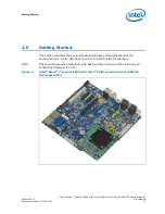
2.5.13
SPI
SPI serial flash device (P/N# SST25VF016B) on the COM Express module stores the
boot code. The boot firmware can be programmed through an in-system programming
tool from Dediprog. A 2x4 2.54 mm pin header is provided on board for use to program
for more information.
The carrier board provides one serial peripheral interface (SPI) from the Intel
®
PCH
EG20T for use in the system. The Intel
®
PCH EG20T SPI is connected to the 2x5
2.54mm pin header (X38) directly.
This port can be used to connect the protocol analyzer of Total Phase Beagle*
I
2
C*/SPI/MDIO.
2.5.14
CAN
The carrier board provides a CAN interface from the Intel
®
PCH EG20T for use in the
system. This CAN controller performs communication in accordance with BOSCH CAN
Protocol Version 2.0B Active
1
(standard format and extended format). The bit rate can
be programmed to a maximum of 1Mbit/s based on the technology used. The Intel
®
PCH EG20T CAN bus is connected to the 1x4 2.54mm pin header (X39) via CAN
transceiver NXP TJA1040T*.
When communicating in a CAN network, individual message objects (see the CAN
Message Objects section in the Message RAM section of the Intel
®
PCH EG20T
datasheet) are configured. The message objects and identifier masks for the receive
filter for the received messages are stored in the message RAM.
2.5.15
Serial ROM
The Intel
®
PCH EG20T provides Serial ROM interface for use of Option ROM data
loading through SPI. This Serial ROM interface has the following two roles.
• Initialization with hardware for Ethernet function and PCI configuration (Packet
Write mode).
— Initialization of MAC-address of Gigabit Ethernet
— Initialization of “Subsystem ID” or “Subsystem Vendor ID” of each PCI device in
the Intel
®
PCH EG20T
• Access to Option ROM space for SATA AHCI function (ROM mode).
It is used to support a single SPI compatible EEPROM device with 8pin DIP socket
(X32). This SPI EEPROM device has some limitations. The following are
requirements for selecting connectable SPI EEPROM:
— Supporting 5 MHz Read and Write
— Supporting Page Write Mode more than 4 bytes
— Memory size is up to 512 Kbit from 8 Kbit
Microchip 25LC512-I/P* meets the requirements mentioned above and is installed on
the SPI EEPROM Socket (X32) on the carrier board.
Note:
Please use the following utilities for programming the Serial EEPROM for MAC address
or SATA AHCI Option ROM
(link:
http://sourceforge.net/projects/generalembedded/files/
)
—
phub_util_orom.tar.b
z2
— phub_util_mac.tar.bz
2
1. Defined by ISO 11519, ISO 11898, and SAEJ2411.