


Intel
®
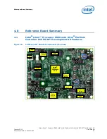
Atom™ Processor E660 with Intel
®
Platform Controller Hub EG20T Development Kit
January 2012
User Manual
Document Number: 324213-002
25
Getting Started
Note:
For the UART0 port, it is necessary to configure switches and jumpers for RS
for details.
Caution:
Do not change the setting after powering on the system. Be careful to configure proper
setting if the intention is to change the setting. A fault in the setting could damage the
platform, the interconnecting cable, or the attached external device.
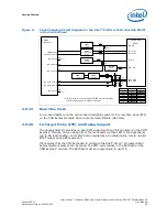
2.5.12
I
2
C*
The carrier board provides one I
2
C* port from the Intel
®
PCH EG20T that conforms to
the typical I
2
C* bus specification. It operates as a master or slave device and supports
a multi-master bus. The Intel
®
PCH EG20T I
2
C* port is connected to the 1x4 2.54mm
pin header (X37) and 2x5 2.54mm pin header (X38) directly.
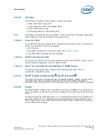
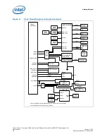
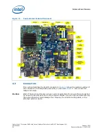
Figure 7.
Intel
®
Platform Controller Hub EG20T UART Port0 Connection Diagram in the
Carrier Board
DCD/GND
RXD/CTS+
D-Sub9pin
Connector (X19)
DTR/RXD+
TXD/RTS+
2
3
1
4
RS232C/RS485
GND/RXD-
DSR/CTS-
RTS/RTS-
CTS/TXD+
RI/TXD-
5
6
7
8
9
MHS121
(SW3)
MAX3245E
MAX3076E
RE
DE
MAX3076E
RE
DE
DGND
DGND
DGND
DTR
DCD
DSR
RI
RTS
CTS
TXD
RXD
D33V
D33V
DGND
Intel® PCH
EG20T
10pin-Header
(X46)
J17
J18
J19
J20
J12
J13
J14
J15
J16
DGND
D33V
J21
MHS442
(SW1)
MHS442
(SW2)