


Intel
®
Atom™ Processor E660 with Intel
®
Platform Controller Hub EG20T Development Kit
January 2012
User Manual
Document Number: 324213-002
21
Getting Started
2.5.8
USB Connectors
The carrier board has six USB Host ports with stackable standard Type-A receptacles
(X20 – X23) for rear panel, two USB Host ports with 10 pin header (X31) for front panel
and one USB client port with mini B receptacle (X45) for front panel. The functionality
of these ports are provided by the Intel
®
PCH EG20T.
Note:
The two USB Host ports that are routed to the front panel side’s pin header (X31) from
the Intel
®
PCH EG20T can be connected to the mini PCIe* slot. The mini PCIe* slot
USB port is enabled by stuffing resistors on R409 and R410 and removing resistors on
R407 and R408.
Each USB Host port on the carrier board has a USB high side switch that is a low
current output type (ROHM BD2052AFJ* Continuous current load: 0.50A by a port) in
the VBUS output for the purpose of validating the Intel
®
PCH EG20T. Therefore,
additional power supply may be necessary depending on the USB device to connect.
describes the carrier board USB-Host interface connection.
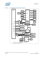
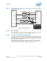
Figure 4.
SATA Block Diagram in the Carrier Board
Intel® PCH
EG20T
SATA #1
Connector
(X29)
SATA ch0
SATA0 TX/RX
SATA0_LED
D5
SATA #2
Connector
(X30)
SATA ch1
SATA1 TX/RX
SATA1_LED
D6
SIO
SMSC I/O
HDD_Indicator
PinHeader
X44
1
3
D50VS
330
D33VS
75
D33VS
75