background image

7

En

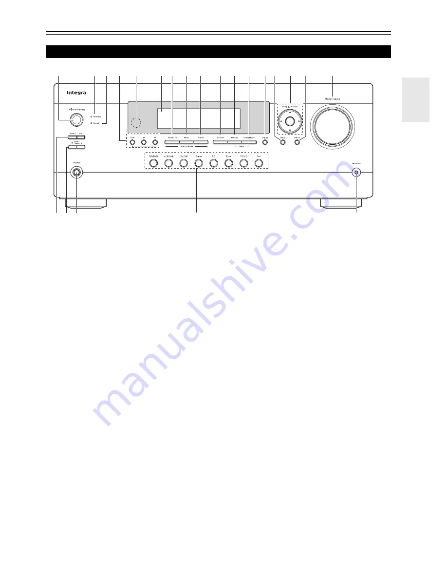
Front & Rear Panels

The actual front panel has various logos printed on it. They are not shown here for clarity.
The page numbers in parentheses show where you can find the main explanation for each item.

a

On/Standby

 button (

20

)

b

Standby

 indicator (

20

)

c

Zone 2

 indicator (

52

)

d

Tone


and 

Tone Level

 buttons (

50

52

)

e

Remote control sensor (

4

)

f

Display (

8

)

g

Movie/TV

 button (

29

)

h

Music

 button (

29

)

i

Game

 button (

29

)

j

Dimmer

 button (

21

)

k

Memory

 button (

27

)

l

Tuning Mode

 button (

26

)

m

Display

 button (

21

)

n

Setup

 button (

35

)

o

Tuning

Preset

 (

26

 to 

27

), Arrow, and 

Enter


buttons

p

Return

 button

q

Master Volume

 control (

21

)

r

Zone 2

 and 

Off

 buttons (

52

)

s

Zone 2 Level

 buttons (

52

)

t

Phones

 jack (

23

)

u

Input Selector buttons (

21

)

v

Setup Mic

 jack (

24

)

Front Panel

t

v

u

b c d  e

f g h i

j k l mn o p

q

rs

Summary of Contents for DTR-20.2

Page 1: ...AV Receiver DTR 20 2 Instruction Manual...

Page 2: ...the apparatus does not operate normally by fol lowing the operating instructions Adjust only those controls that are covered by the operating instructions as an improper adjustment of other controls m...

Page 3: ...amp If water or any other liquid gets inside this unit have it checked by the dealer from whom you purchased this unit 8 Handling Notes If you need to transport this unit use the original packaging to...

Page 4: ...Note If the remote controller doesn tworkreliably try replacing the batteries Don t mix new and old batteries or different types of batteries If you intend not to use the remote controller for a long...

Page 5: ...ening Modes 29 Selecting Listening Modes 29 About Listening Modes 30 Advanced Setup 35 On screen Setup Menus 35 Common Procedures in Setup Menu 35 Input Output Assign 36 Speaker Setup 37 Audio Adjust...

Page 6: ...80 5 978 762 6 226 616 6 487 535 7 212 872 7 333 929 7 392 195 7 272 567 other U S and worldwide patents issued pending DTS is a registered trademark and the DTS logos Symbol DTS HD and DTS HD Master...

Page 7: ...Tone Level buttons 50 52 e Remote control sensor 4 f Display 8 g Movie TV button 29 h Music button 29 i Game button 29 j Dimmer button 21 k Memory button 27 l Tuning Mode button 26 m Display button 2...

Page 8: ...NTENNA jack and AM ANTENNA terminal f MONITOR OUT V jack g UNIVERSAL PORT jack h IR IN A B and OUT jacks i 12V TRIGGER OUT jacks j SPEAKERS terminals CENTER FRONT SURR k RS232 jack l ZONE 2 PRE OUT ja...

Page 9: ...tton 21 j Return button k Home button 22 l Sleep button 22 Controlling the tuner To control the AV receiver s tuner press Tuner or Receiver You can select AM or FM by pressing Tuner repeatedly a Arrow...

Page 10: ...c Surround speakers These speakers are used for precise sound positioning and to add realistic ambience Position them at the sides of the listener or slightly behind about 2 to 3 feet 60 to 100 cm abo...

Page 11: ...fore connecting your speakers You can connect speakers with an impedance of between 6 and 16 ohms If you use speakers with a lower imped ance and use the amplifier at high volume levels for a long per...

Page 12: ...k speaker connect it to the PRE OUT SURR BACK jacks Connect your Power amplifier s analog audio output jacks to the AV receiver s PRE OUT SURR BACK jacks with an audio cable Note The speakers are conf...

Page 13: ...b c c d d e e TV screen TV screen Dipole speakers Normal speakers You can use dipole speakers for the surround and surround back speakers Dipole speakers output the same sound in two directions Dipol...

Page 14: ...AV Connections Signal Cable Jack Description Video and Audio HDMI HDMI connections can carry digital video and audio Video Component video Component video separates the luminance Y and color differen...

Page 15: ...nent so that its video can be seen on the TV screen on the TV select the input of the HDMI component connected to the AV receiver If the TV power is off or the TV is set to another input source this m...

Page 16: ...SAT Satellite cable set top box etc OUT TV projector etc B DIGITAL IN OPTICAL IN 1 GAME Digital audio Game console IN 2 TV CD TV CD player COAXIAL IN 1 BD DVD Blu ray Disc DVD player IN 2 CBL SAT Sate...

Page 17: ...to Power On When you start playback on a component connected via u while the AV receiver is on Standby the AV receiver will automatically turn on and select that com ponent as the input source Direct...

Page 18: ...on the AV receiver may cause a momentary power surge that might interfere with other electrical equipment on the same circuit If this is a problem plug the AV receiver into a different branch circuit...

Page 19: ...nput will be selected And if no component video input is assigned to the input selector this will be interpreted as no component video signal being present In the Signal Selection Example shown on the...

Page 20: ...AV receiver comes on the display lights and the Standby indicator goes off Turning Off Press On Standby on the front panel or the remote controller The AV receiver will enter Standby mode To prevent...

Page 21: ...he HDMI OUT If your TV is connected to the MONITOR OUT V or the COMPONENT VIDEO OUT use the AV receiver s display when changing settings This manual describes the procedure using the remote controller...

Page 22: ...muted and the MUTING indicator flashes on the display Using the Sleep Timer Press Receiver followed by Sleep repeatedly to select the required sleep time The sleep time can be set from 90 to 10 minute...

Page 23: ...ening area in both the frequency and time domain The result is clear well balanced sound for every one Enabling Audyssey 2EQ allows you to also use Audyssey Dynamic EQ which maintains the proper octav...

Page 24: ...hile a pair of headphones is connected 1 Turn on the AV receiver and the connected TV On the TV select the input to which the AV receiver is connected TV Listening area a to c Listening position 2 Set...

Page 25: ...priate settings 11 Changing the Speaker Settings Manually You can manually make changes to the settings found dur ing Audyssey 2EQ Room Correction and Speaker Setup See also Speaker Configuration 37 S...

Page 26: ...uency This section describes the procedure using the but tons on the front panel unless otherwise specified Using the Tuner Press Tuner to select either AM or FM In this example FM has been selected E...

Page 27: ...See the previous section 2 Press Memory The preset number flashes 3 While the preset number is flashing about 8 sec onds use Preset e r to select a preset from 1 through 40 4 Press Memory again to sto...

Page 28: ...be recorded to a video recorder e g VCR DVD recorder connected to the VCR DVR OUT jack Recording from Different AV Sources You can overdub audio onto your video recordings by simultaneously recording...

Page 29: ...s Game THX Movie TV Music Press Receiver first Movie TV Music Game The Dolby Digital and DTS listening modes can only be selected if your Blu ray Disc DVD player is connected to the AV receiver with a...

Page 30: ...eakers D This is 5 1 channel surround sound This surround system has five main channels of sound and a sixth sub woofer channel called the point one channel F This is 7 1 channel surround sound This i...

Page 31: ...Movie Use this mode with any stereo or Dolby Surround Pro Logic movie e g TV DVD VHS Dolby PLIIx Music Use this mode with any stereo or Dolby Surround Pro Logic music source e g CD radio cassette TV V...

Page 32: ...his mode is for use with DTS ES Matrix soundtracks which use a matrix encoded back channel for 6 1 7 1 channel playback Use it with DVDs that bear the DTS ES logo especially those with a DTS ES Matrix...

Page 33: ...is often mixed similarly to movies but in a smaller environment THX Loudness Plus is configured for game audio levels with Timbre Matching active D F G CN The combination of Dolby Pro Logic II IIx 1...

Page 34: ...nd field with a powerful acoustic image like being at a club or rock concert TV Logic This mode adds realistic acoustics to TV shows produced in a TV studio surround effects to the entire sound and cl...

Page 35: ...Calibration 4 Equalizer Settings 5 THX Audio Setup 2 Speaker Setup 1 Multiplex Mono 2 Dolby 3 DTS 4 Theater Dimensional 5 LFE Level 3 Audio Adjust 1 Audyssey 2 IntelliVolume 3 A V Sync 4 Name Edit 5...

Page 36: ...HDMI3 HDMI4 HDMI5 Select a corresponding HDMI input that the video component has been connected Select this to output composite video and component video sources from the HDMI OUT The video sig nal fr...

Page 37: ...you connect a component such as UP A1 Dock that seated iPod to the UNIVERSAL PORT jack you cannot assign any input to Port selector Main menu Speaker Setup Here you can check the settings made by Aud...

Page 38: ...ps meters Distances can be set in meters Range 0 15m to 9 0m in 0 15 meter steps Left Center Right Surr Right Surr Back Right Surr Back Left Surr Left Subwoofer Specify the distance from the each spea...

Page 39: ...GC On Select this to turn on BGC Note This setting is only available if THX Ultra2 Select2 Sub woofer is set to Yes Loudness Plus Off Select this to turn off Loudness Plus On Select this to turn on Lo...

Page 40: ...c IIx Music listening mode Higher settings move the sound field backward Lower settings move it forward If the stereo image feels too wide or there s too much surround sound move the sound field forwa...

Page 41: ...selected Reference Level Audyssey Dynamic EQ Reference Level Offset 0dB It should be used when listening to movies 5dB Select this setting for content that has a very wide dynamic range such as classi...

Page 42: ...ignal To view the TV picture while setting the delay press Enter To return to the previous screen press Return If HDMI Lip Sync is enabled 47 and your TV or dis play supports HDMI Lip Sync the display...

Page 43: ...This setting determines the aspect ratio Note When the Game Mode is set to On this setting is fixed at Full 4 3 1 Use q w e r to select a character and then press Enter Repeat this step to enter up to...

Page 44: ...or 2 2 Auto Adjusts to the picture source automatically selecting Picture Mode 3 2 Selected when the picture source is movie film etc 2 2 Selected when the picture source is computer graph ics animati...

Page 45: ...io signal is played Mono Multiplex Source With this setting you can specify the listening mode to be used when a mono digital audio signal is played DVD etc 2ch Source With this setting the default li...

Page 46: ...if there s a volume difference between your speakers and your head phones OSD Setup On Screen Display This preference determines whether operation details are displayed on screen when an AV receiver f...

Page 47: ...le component is connected to the AV receiver via the HDMI cable the name of the connected component is displayed on the AV receiver display For example while you are watching TV broadcasting if you op...

Page 48: ...akers Note To bypass the bass and treble tone circuits select the Direct or THX listening mode Alternatively you can use the AV receiver s Tone and 50 Speaker Levels You can adjust the volume of each...

Page 49: ...6 Cinema and 5 1 channel source Neo 6 Re EQ THX Off Re EQ THX Function off On Re EQ THX Function on This function can be used with the following listening modes THX Cinema THX Surround EX and THX Sel...

Page 50: ...ed instead PCM Only 2 channel PCM format input signals will be heard If the input signal is not PCM the PCM indi cator will flash and noise may also be produced DTS Only DTS but not DTS HD format inpu...

Page 51: ...ceiver Zone 2 Maximum Volume Off 50 to 99 Absolute display Off 32dB to 17dB Relative display With this setting you can limit the maximum volume To disable this setting select Off Zone 2 Power On Volum...

Page 52: ...select an input source press Zone 2 followed by an input selector button within 8 seconds Zone 2 turns on the Zone 2 indicator lights To select AM or FM press the Tuner input selector button repeated...

Page 53: ...nt of current may be drawn momentarily To prevent this you can delay trigger signals A B and C individually Another application for trigger delay is eliminating the thump noise that s sometimes heard...

Page 54: ...remote controller and feeds them to the AV receiver located in the cabinet via the connecting block Using a Multiroom Kit with Other Components In this setup an IR emitter is connected to the AV recei...

Page 55: ...d the power consumption on standby mode slightly increases You can control your iPod when Port is selected as the input source See the UP A1 Dock s instruction man ual for more information 56 B RI Doc...

Page 56: ...s PORT Reading The AV receiver is checking the connection with the dock PORT Not Support The AV receiver do not support the connected dock PORT UP A1 UP A1 Dock is connected Note The AV receiver displ...

Page 57: ...the Alarm Clock function on your iPod to start playback the AV receiver will automatically turn on at the specified time and select your iPod as the input source Note Linked operations do not work wi...

Page 58: ...and select your music while looking at your TV Extended mode Video Playlists Movies Music Videos TV Shows Video Podcasts or Rentals are displayed on your TV and you can navigate and select your video...

Page 59: ...r Setup TV BD DVD VCR DVR CBL SAT GAME PC TV CD 8 1 Remote Mode Setup TV TV DVD TV VCR 8 1 Remote Mode Setup TV 5 Use q w to select category and then press Enter The brand name input panel appears 6 U...

Page 60: ...y category e g DVD player TV etc 2 While holding down Remote Mode to which you want to enter a code press and hold down Dis play about 3 seconds The Remote indicator lights Note Remote control codes c...

Page 61: ...D is preprogrammed with the remote control code for controlling a component that supports the p 1 limited to some models The component must be able to receive remote control commands via p and be conn...

Page 62: ...trolling Your iPod about the operation of iPod 57 c d a b i e f h g j k o m l n Press the appropriate Remote Mode first TV DVD player DVD recorder Blu ray Disc player HD DVD player VCR PVR Satellite r...

Page 63: ...nd reconnect your speakers and input sources If the AV receiver turns off when you set the volume to maximum disconnect the power cord and contact the dealer from whom you purchased this unit Audio Ma...

Page 64: ...Video discs you need to select an audio output format from a menu Depending on the input signal some listening modes cannot be selected 30 34 If no surround back speakers are connected 6 1 7 1 playba...

Page 65: ...Install new batteries Don t mix different types of batteries or old and new batteries 4 Make sure that the remote controller is not too far away from the AV receiver and that there s no obstruction b...

Page 66: ...n 17 This can be caused by any malfunction in your speaker unit Check if the unit produces normal sounds The AV receiver contains a microcomputer for signal processing and control functions In very ra...

Page 67: ...eristics 10 dB 50 Hz BASS 10 dB 20 kHz TREBLE Signal to Noise Ratio 106 dB LINE IHF A Speaker Impedance 6 16 Input Sensitivity Output Level and Impedance 1 Vp p 75 Component Y 0 7 Vp p 75 Component PB...

Page 68: ...tal video signals Other devices connected to the AV receiver via HDMI must also support HDCP 1 DVI Digital Visual Interface The digital display interface standard set by the DDWG 3 in 1999 2 HDCP High...

Page 69: ...u ray Disc DVD player is up to three Blu ray Disc recorder DVD recorder Digital Video Recorder is up to three Cable Satellite Set top box is up to four Do not connect the AV receiver to the other AV r...

Page 70: ...speakers from the menu screen of the TV and confirm that the audio is output from the speakers of the TV and not from the speakers connected to the AV receiver 6 Select Use the speakers connected from...

Page 71: ...AV receiver Output 1 Available resolution 640 480 60 72 75 Hz 800 600 56 60 72 75 Hz 1024 768 60 70 75 Hz 1280 1024 60 Hz HDMI COMPONENT COMPOSITE 1080p 1080i 720p 480p 480i 1080p 1080i 720p 480p 480...

Page 72: ...Nisshin cho Neyagawa shi OSAKA 572 8540 JAPAN Tel 072 831 8023 Fax 072 831 8163 En 2 9 4 0 0 2 8 1 SN 29400281 C Copyright 2010 ONKYO CORPORATION Japan All rights reserved Y1003 1 Integra Division of...

Reviews: