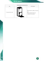
Disassembly and Assembly of the Electric Box
Step
Picture
Work instruction
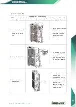
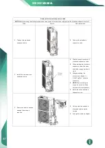
3. Remove the electric element.
Disconnect the electric element from the
wiring terminal.
Loosen screws around th e electric
element with a screwdriver.
Remove the electric element from the
electric box.
4. Mount the new electric
element.
Place the electric element at the proper
position.
Tighten the screws around the electric
element with a screwdriver.
Wire the electric element to the wiring
terminal.
5. Reinstall the electric box.
Place the electric box at the proper
position.
Tighten screws around the electric box
with a screwdriver.
Connect the power cord and control line
properly.
Reassemble the unit as before.
Disassembly and Assembly of the Fan Motor
Step
Picture
Work instruction
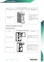
1. Remove the upper panel.
Loosen screws round the upper panel
with a screwdriver.
Remove the upper panel from unit.
SERVICE MANUAL
99
Summary of Contents for Inverter FLEX24 DEV24H2R18
Page 9: ...6 SERVICE MANUAL 2 Control 2 1 Operation Mode 2 1 1 Cooling Mode ...
Page 10: ...2 1 2 Heating Mode SERVICE MANUAL 7 ...
Page 19: ...Model DEV48H2R18 DEV60H2R18 16 SERVICE MANUAL ...
Page 27: ...SEV2040H2R18 SEV4060H2R18 24 SERVICE MANUAL ...


