


Configuration manual
Configuration
7
Chapter 2
Configuration
Once the installation and cabling procedures have been completed (refer to the Installation Manual of the Previdia Max
system) the system is ready for first startup.
In the case of first start-up, the selection of the control panel languages is requested, a compulsory main lnaguage and
an optional secondary language (see
paragraph 2.10
).
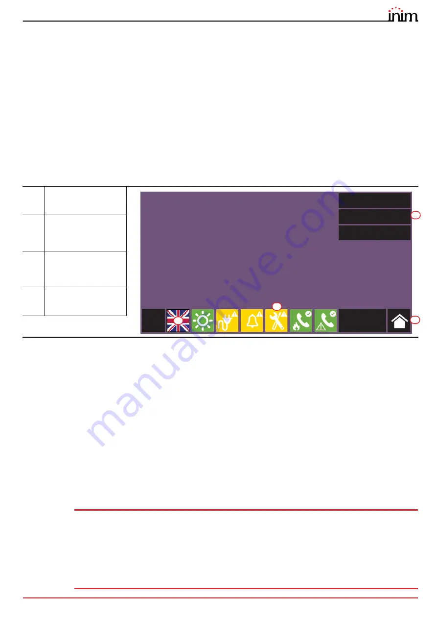
The control panel screen will be as follows:
In this condition the control panel has no acquired configuration, all the modules connected to the CAN drive bar or
front plate have the same address and are not included in the configuration.
The configuration status icon on the status bar indicates a fault condition, due to the fact that modules have been
detected but are not present in the configuration saved in the memory.
In order to configure the control panel it is necessary to work through the following procedure:
1.
Access programming (
paragraph 2.1
)
2.
Set the IP network address (
paragraph 2.2
)
3.
Access the configuration menu (
paragraph 2.3
)
4.
Assign addresses to the system modules (
paragraph 2.4
)
5.
Enroll loop devices on IFM2L modules and respective troubleshooting procedure (
paragraph 2.7
)
6.
Set the defined configuration (
paragraph 2.8
)
7.
Check eventual signalling and search for faults (
paragraph 2.9
)
8.
Set the date and time (
paragraph 2.11
)
Note:
Once the configuration operations have been completed correctly, the control panel will be ready to
operate.
The control panel is configured to consider each input point (detector, module, terminal) as a fire-alarm
point. Therefore, in the event of a fire alarm it will activate all the outputs available on its loops or
terminals.
At this point it is necessary to proceed with eventual changes to the configuration data for the
distribution of points in zones, edit descriptions of the various system elements, define specific
activation sequences, etc.
Refer to the Programming manual.
[A]
Buttons to access the
events logs, system
status and programming.
[B]
Status bar (always
present) shows essential
information regarding
the system.
[C]
Button for changing the
language of the control
panel, if a secondary
language is provided
[D]
Configuration status
icon (system
configuration and faults)
Log
System status
Programming
L: 1
01/01/2020
18:23
C
B
A
D


