32
2
3
2
3
1
3
1
2
2
2
1
3
3
2
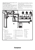
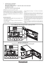
KIT INSTALLATION.
- Remove voltage from the appliance by disconnecting the switch
upstream from the boiler.
- Disassemble the boiler casing (see instruction booklet relative
to the boiler model).
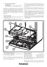
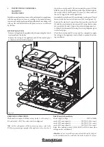
- Open the control panel compartment to install the relay board
(1).
- Mount the board making the male pin (2) match the hole in the
board (1) and fix it using the cross-head screw (3) (see figure
1-1).
- Make the electric connections between the relay board (1) and
the boiler P.C.B., placed on the control panel rear, using the
relative wiring composed of two cables supplied with the kit.
- The connection cable between the relay board and the boiler
board must comply with the path indicated by the arrows (fig.
1-1).
- The power supply must be connected to terminals A and B.
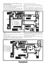
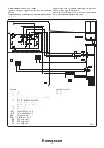
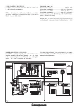
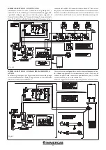
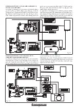
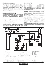
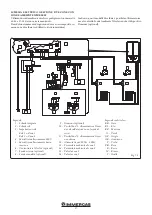
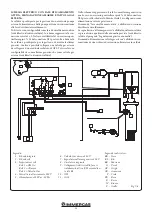
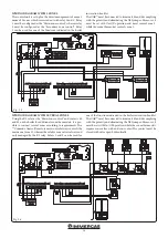
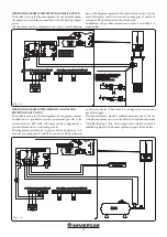
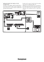
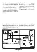
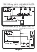
- Connect the external components according to the require-
ments following the wiring diagrams given on the next pages.
- Close the control panel, re-mount the casing and re-apply the
voltage to the appliance to take it back to normal functioning
conditions.
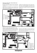
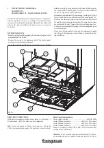
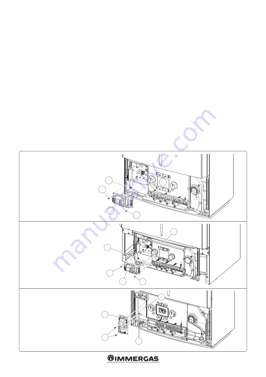
Fig. 1-1
Victrix Maior TT
Victrix Maior 35 TT PLUS
Victrix TT ErP
1
INSTRUCTIONS FOR MODELS:
VICTRIX MAIOR TT - VICTRIX MAIOR 35 TT PLUS
VICTRIX KW TT - VICTRIX KW TT PLUS
VICTRIX TT ERP
VICTRIX ZEUS
Victrix Zeus
Victrix KW TT
Victrix KW TT PLUS

