

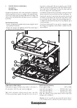
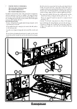

55
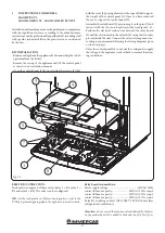
1
2
3
4
5
6
7
8
9
9
12
9
10
11
13
14
15
16
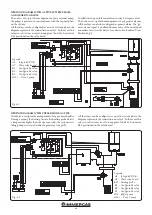
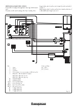
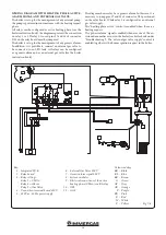
Fig. 7-2
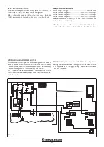
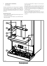
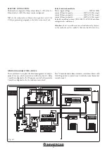
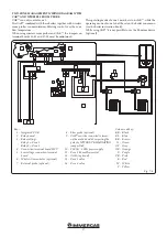
ELECTRIC CONNECTION.
The board consists of three relays (relay 1 = K1; relay 2 = K2
and relay 3 = K3). The relays can be configured according to
the boiler model. Therefore, different functions can be obtained
depending on the connection (see boiler instruction booklet).
N.B.:
for the configuration of the functioning options, refer to the
electronic board Configuration Menu of the boiler instruction
book.
Relay board technical data.
Power supply voltage: ............................................. 230VAC 50Hz
Contact K1 max capacity: ........................230VAC 1.00A cosφ 1
Contact K2 max capacity: ........................230VAC 0.75A cosφ 1
Contact K3 max capacity: ........................230VAC 0.75A cosφ 1
Relay K2 enabling contact (X25) SELV 24VDC 10mA (low
voltage in safe conditions)
Attention:
do not exceed the maximum load allowed by the fuses
on the mother board (it is added to the boiler load) (3.15A fuse).
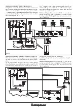
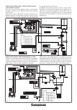
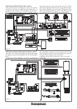
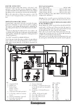
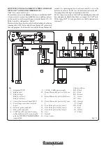
WIRING DIAGRAM WITH 2 ZONES.
The relay board, connected to the boiler, is set up for the mana-
gement of a maximum of 2 zone actuators (valves or pumps);
the actuators can be managed by appropriately configuring the
relays through the boiler menu (see the boiler instruction book).
N.B.:
- Only after configuring the relay board as zone 2 control , the
possibility of controlling zone 2 will appear on the boiler display
(through time schedules and temperatures or through external
Room Thermostats)
- The CAR
V2
can only be combined with zone 1.
Victrix Superior boiler offers the possibility of using different
room controls, such as Room Thermostats, CAR
V2
, Wireless
room probes; Some examples of electrical connections are
given below.
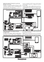
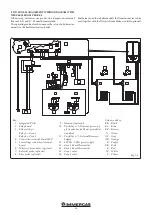
TWO-ZONE MANAGEMENT WIRING DIAGRAM WITH
ROOM THERMOSTATS
Room Thermostats will be connected to contacts 40 and 41 (for
zone 1) and 57-58 (for zone 2). Please note that the consent to
switch on the heating of each zone is managed in 'AND' between
the Room Thermostat contact and the zone program.
If you want to use only the room thermostat control, the ope-
rating mode of each zone must be set on the boiler zone menu
as 'MAN' (see the boiler instruction book).
Furthermore, on these boiler models, the Dominus device can
be used together with the Room Thermostats control (optional).
Key:
1 - Integrated P.C.B.
2 - Relay board
3 - Relay settings:
Relay 1 = Zone 1
Relay 2 = Zone 2
4 - Connection terminal board 230 V
5 - Low voltage connection terminal
board
6 - Wireless Concentrator (optional)
7 - External probe (optional)
8 - Flow probe (optional)
9 - Dominus (optional)
10 - Possibility n °1: Dominus power sup-
ply from boiler (cable not provided as
standard)
11 - Possibility n °2: External Dominus
Supply
12 - 230 Vac - 50 Hz power supply
13 - Zone 1 Room Thermostat
14 - Zone 2 Room Thermostat
15 - Zone 1 valve
16 - Zone 2 valve
Colour code key:
BK - Black
BL - Blue
BR - Brown
G - Green
GY - Grey
OR - Orange
P - Purple
PK - Pink
R - Red
W - White
Y - Yellow


