

56
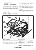
1
2
3
4
5
6
7
8
9
9
12
9
10
11
13
14
15
16
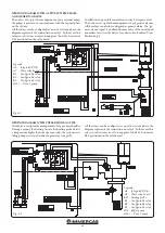
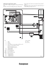
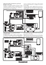
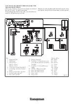
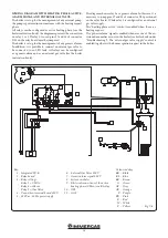
Fig. 7-3
Key:
1 - Integrated P.C.B.
2 - Relay board
3 - Relay settings:
Relay 1 = Zone 1
Relay 2 = Zone 2
4 - Connection terminal board 230 V
5 - Low voltage connection terminal
board
6 - Wireless Concentrator (optional)
7 - External probe (optional)
8 - Flow probe (optional)
9 - Dominus (optional)
10 - Possibility n °1: Dominus power sup-
ply from boiler (cable not provided as
standard)
11 - Possibility n °2: External Dominus
Supply
12 - 230 Vac - 50 Hz power supply
13 - Zone 1 Room Thermostat
14 - Zone 2 Room Thermostat
15 - Zone 1 valve
16 - Zone 2 valve
Colour code key:
BK - Black
BL - Blue
BR - Brown
G - Green
GY - Grey
OR - Orange
P - Purple
PK - Pink
R - Red
W - White
Y - Yellow
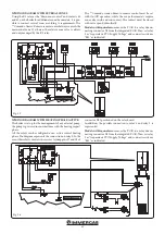
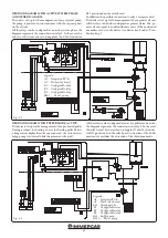
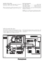
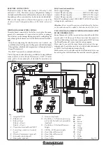
TWO-ZONE MANAGEMENT WIRING DIAGRAM WITH
WIRELESS ROOM PROBES
When using wireless room probes, the jumpers on terminal
boards 40-41 and 57-58 must be maintained.
The operating mode of each zone must be set on the boiler zone
menu (see the boiler instruction book).
Furthermore, on these boiler models, the Dominus device can be
used together with the Wireless Room Probes control (optional).


