
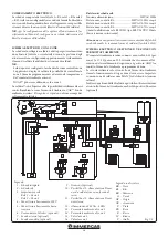
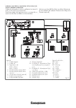


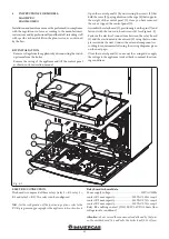
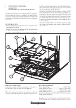

36
Fig. 1-7
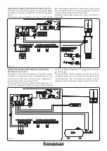
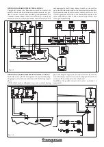
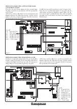
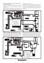
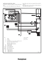
WIRING DIAGRAM WITH CHILLER CONTROL
(COOLING ONLY).
The boiler is set up to manage a chiller. The supply voltage oc-
curs simultaneously with the request from the Comando Amico
Remoto remote control
V2
. In the event this configuration is
used, it is necessary to jump pins 57 and 58 of connector X25
positioned on the relay board.
The CAR
V2
must be connected to terminals 41 and 44 complying
with the polarity and eliminating jumper X40.
Attention:
to prevent the chiller electronic control from dam-
age, the signal control must not be live. Interrupt a 230V relay
between the chiller and relay board as indicated in the diagram.
All the relays can be configured. Set relay 3 as "Chiller remote
activation".
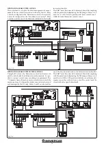
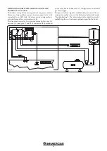
INTEGRATED P.C.B.
INTEGRATED P.C.B.
CONNECT THE CHILLER
CONNECT THE CHILLER
ACTIVATION (CONTACT
ACTIVATION (CONTACT
NOT POWERED)
NOT POWERED)
RELAY BOARD
RELAY BOARD
230 Vac 50
230 Vac 50
Hz power
Hz power
supply
supply
Very low
Very low
safety
safety
voltage
voltage
230V Connection terminal board
230V Connection terminal board
Low voltage connection terminal board
Low voltage connection terminal board
Blu
e
Blu
e
Blu
e
Blu
e
Br
ow
n
Br
ow
n
Br
ow
n
Br
ow
n


