Chapter 3
Operation
26
Bars Display
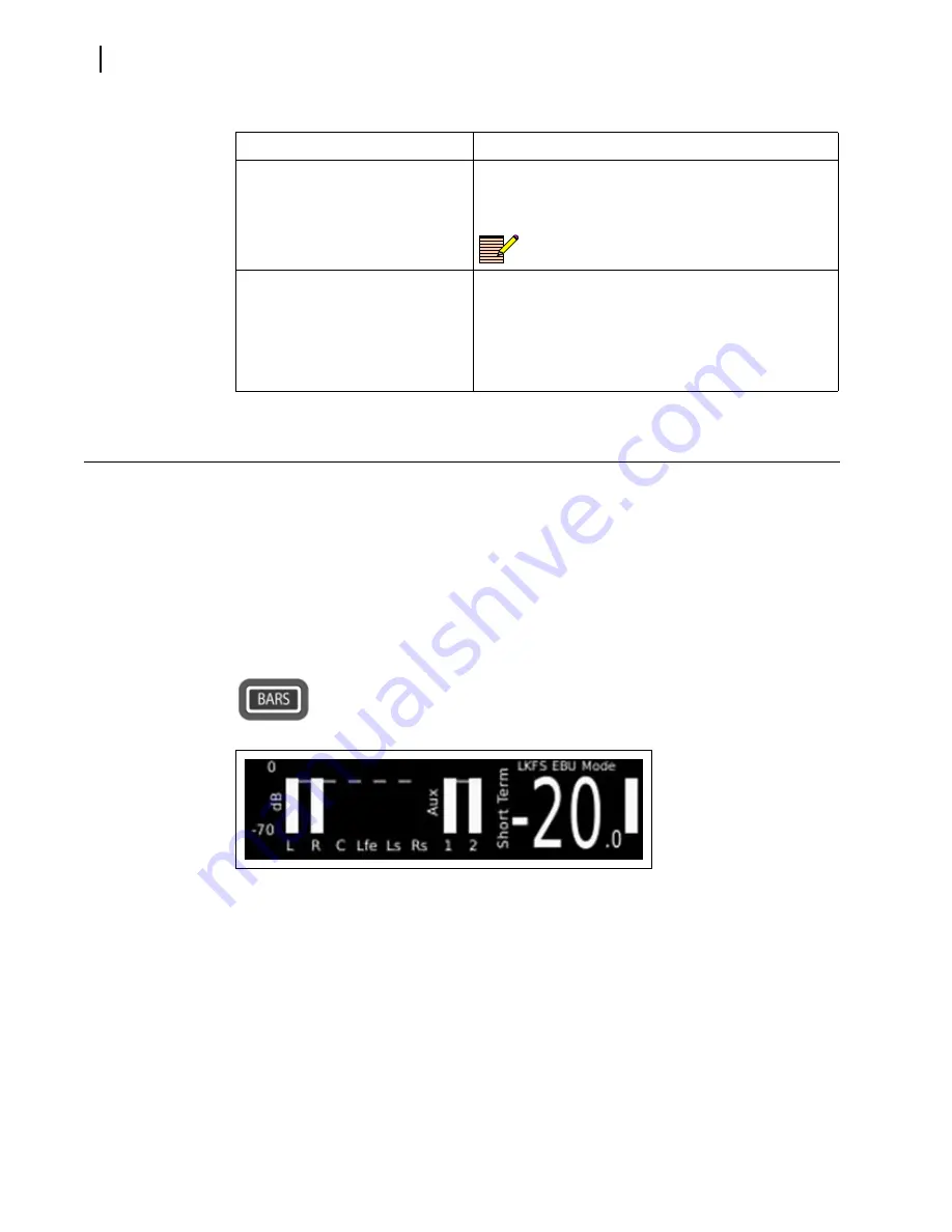
The Bars display shows up to eight true peak audio meters, grouped as 5.1 and an Aux or
stereo pair. The first six meters represent Program 1 data and the remaining two meters
represent Program 2. The large text represents the short-term loudness and the vertical bar
represents the momentary loudness.
The LLM-1770 supports up to eight individual audio meters. Meter displays are associated
or mapped to physical inputs through menu options.
To display the bargraph meters
Press and release the
BARS
button. The Bars display is shown in
Figure 3-4
.
The dashed line represents the target loudness as entered through the menu
system
Figure 3-4
Bars Display
To access the Meter Mapping setup menu
Press and hold the
BARS
button; or, press the
SETUP
button, and then use the navigation
buttons to scroll through the menu selections.
Meter mapping allows any input source to be mapped to any meter. The meter names are
fixed and are assigned to meters 1 through 8 from left to right; that is, L = meter 1,
R = meter 2.
To leave the Meter Mapping setup menu
Press the
SETUP
or the
EXIT
button.
Loudness
Current loudness mapping
M= Meter indicator
# = Meter number of source
Loudness mapping is meter-based, not
input-based.
Headphone
Current headphone mapping (headphone mapping is
input based, not meter based)
E = Embedded
A = AES
D = Dolby Decoder
# = Channel number for headphones
Table 3-3
Status Information Descriptions
Field Name
Description
Summary of Contents for Videotek LLM-1770
Page 13: ...LLM 1770 Installation and Operation Manual 7 Figure P 3 WEEE Compliance Symbol...
Page 14: ...About This Manual 8...
Page 62: ...Chapter 4 Setup Menu Functions 56...
Page 68: ...Chapter 5 Alarm Descriptions 62...
Page 76: ...Chapter 6 External Control 70...
Page 84: ...Chapter 8 Specifications 78...
Page 102: ...Appendix C Glossary 96...
Page 122: ...Index 116...


