


O P E R A T I O N S
Connecting to the Laser Current Source
10
LDC-3926339
C H A P T E R
2
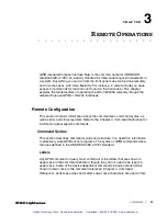
Laser Diode Connection
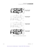
A Combo-D connector on the rear panel of the current source module is used to
connect laser diodes to the module. There are connections provided for laser
cathode and anode, photodiode cathode and anode, chassis ground, interlock,
and laser forward voltage.
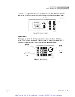
Figure 2.2
Back Panel Laser Diode Connector
Interlock Connections
To enable the laser output, a short must exist between the Interlock pins (pins 1
and 2) of the connector. The short can be a direct short across the pins or a switch
to prevent laser operation until the switch is closed. If laser output is turned on
without a short between pins 1 and 2, an error appears for the respective channel
on any of the laser set-up pages or on the status screen. Furthermore, the output
is turned off and error E501 (see
Front panel Error Indicators
on page
79
) appears
if the interlock is disconnected.
The interlock terminals on the laser connector, pins 1 and 2, must be isolated from all
other connections including earth ground.
Four-Wire Voltage Sense
The LDC-3926339 has a 4-wire voltage sense feature. The laser voltage is
sensed through a pair of connections (pins 4 and 9) that are separate from the
laser current drive connections (pins A2 and A3). This allows a more accurate
laser voltage reading. All four of these pins (4, A2 , 9, A3) must be connected for
the module to operate. For more information about 4-wire Voltage Sense, see
Tech Note #TN3916-2. Contact ILX Lightwave Customer Service (see page
xii
for
Artisan Technology Group - Quality Instrumentation ... Guaranteed | (888) 88-SOURCE | www.artisantg.com