22
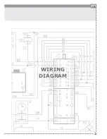
KEYS
WIRING DIAGRAMS
*
ATTENTION
: the letters and numbers in br ackets are optional because the wiring diagr am does not change
from one model to another.
00
Black
11
Brown
22
Red
33
White
44
Yellow
45
Yellow-green
55
Grey
66
Blue
AA
Electrical ignition transformer
C
Switch
F
Phase
K1
Earth wire for terminal board
K2
” ” lower resistance
K3
” ” for oven fan
K4
” ” circular resistance
K5
” ” upper resistance
K6
” ” oven lamp 1
K7
” ” oven lamp 2
K8
” ” rotisserie
K9
” ” cooling fan
K10 ” ” selector
K11 ” ” oven thermostat
K12 ” ” programmer/timer
K13 ” ” grill
K14 ” ” el. hotplate
K15 ” ” appliance chassis
K16 ” ” barbecue
K17 ” ” fryer
L1
Oven lamp
L2
Oven lamp
M
Terminal board
MA
Electrical ignition microswitch
MD
Grill microswitch
MG
Rotisserie
MP
Door microswitch
N
Neutral
P
Minute counter/Programmer
P
Minute counter/Clock
PE
Electric hotplate
R1
Upper heating element
R2
Lower heating element
R3
Grill heating element
R4
Circular heating element
R5
Barbecue heating element
R6
Fryer heating element
RE
Energy regulator
S1
Oven warning light
S2
Mains power warning light
S3
Grill warning light
S4
Cooling fun warning light
S5
Barbecue warning light
S6
El. hotplate warning light
S7
Turnsplit warning light
S8
residual heat warning light
S9
Fryer warning light
SP
Sparking plug
T
Grill thermostat
TF
Oven thermostat
TR
Fryer thermostat
TS
Safety thermostat
TT
Cooling fan thermostat
V
Oven fan
VT
Cooling fan
Ignition scheme of gas hob


