


2
1
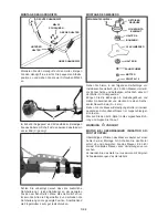
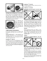
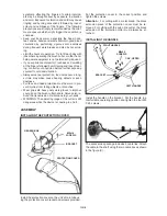
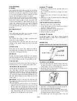
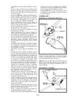
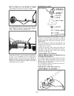
Please make sure that the additional tube holder 1
(see figure) is seated in the indicated position on the
shaft. If this should not be the case loosen the wing nut
2 and slide the tube holder to the indicated position.
Then tighten the wing nut 2 very firmly.
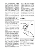
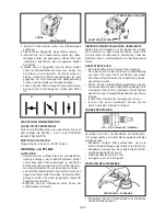
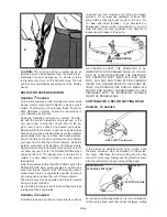
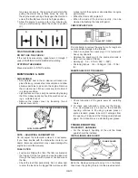
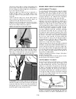
INSTALLING THE BLADE
SPLIT PIN 2x16
ALLEN KEY
GEAR BOX
SAFETY GUARD
BRACKET A
BORE
3-TOOTH BLADE
BRACKET B
TOOTHED WASHER
NUT
Install blade in the following order: Install holder A, the
3-tooth blade, holder B, the toothed washer, then fix all
with the nut with left-handed thread.
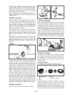
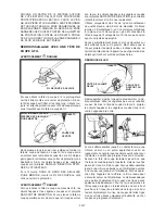
Align the bores in the gear case and holder A and in-
sert an Allen key (S=4mm).
Tighten the blade fastening nut with a matching box
wrench by turning it anti-clockwise.
Install the 2x16 split pin and bend out the ends.
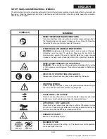
WARNING
ATTENTION
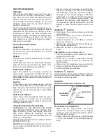
STOP THE ENGINE IMMEDIATELY IF EXCESSIVE
VIBRATION OCCURS !
Excessive vibration of the blade indicates that it is not
properly installed. Stop the engine immediately and
check the blade. An improperly installed blade may
cause injury.
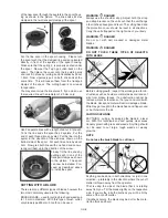
Operate the unit with original cutting tools of the manu-
facturer only.
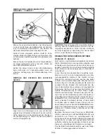
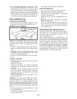
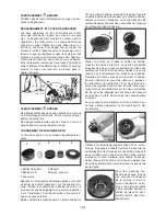
INSTALLING NYLON LINE CUTTING HEAD
WARNING
ATTENTION
Turn the threaded bolt of the drive shaft until the bore
in the adapter plate is exactly aligned with the bore in
the main tube and put in the Allen in to lock the parts
in this position.
Retainer A must be applied. Retainer B, toothed wash-
er, nut and split pin should be kept. These parts are not
required to install the cutting head.
Screw the cutting head on the threaded bolt (turning it
anti-clockwise) until it is tight. Remove the Allen key.
When cutting with the nylon line cutting head, take
care that the black extension of the protection cover
is mounted.
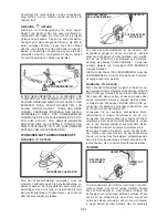
Installing and putting on the shoulder strap
Put the shoulder strap on as shown in the picture. The
hip pad shall rest on the right hip. Hook the snap hook
of the shoulder strap into the bracket provided at the
main tube. Adjust the strap according to your height.
GB-5
Summary of Contents for BT 4344
Page 2: ......
Page 94: ...GR 1 15 ELLHNIKA...
Page 96: ...15 15 GR 3...
Page 97: ...Raynaud GR 4...
Page 98: ...M5xl6 M5x20 M5x25 X 2 X 2 1 1 2 2 2x16 3 A B GR 5...
Page 99: ...A 3 B A S 4 mm 2x16 A B x x GR 6...
Page 100: ...15 16 15 METERS 50 FEET 15 GR 7...
Page 101: ...Monofil 2 5 mm KNIFE SIDE RAISED ANGLE TO GROUND ANGLE TO WALL 2 3 4 5 1 1 2 3 4 5 GR 8...
Page 102: ...1 2 1 5 cm 5 4 3 1 2 2 4 1 5 cm 2 5 mm 2 2 1 m 2 2 cm 15mm 3 255 mm GR 9...
Page 103: ...89 30 1 2 2 30 1 89 30 1 2 30 1 1 2 3 4 3 4 GR 10...
Page 104: ...5 6 1 2 3 4 5 STOPP l Stopp START 2 7 10 CHOKE 3 A 4 5 B 6 7 C A B C 3 7 Stopp STOP GR 11...
Page 105: ...O 6 0 7mm 0 023 O 028 0 6 0 7 mm 145 155 kg cm 1 25 2 GR 12...
Page 106: ...2 GR 13...
Page 107: ...1 0 6 0 7 mm Stop 2 3 0 6 0 7 mm 0 3 0 4 mm 4 GR 14...
Page 108: ......
Page 114: ......
Page 119: ......


