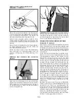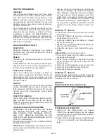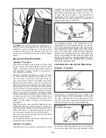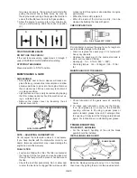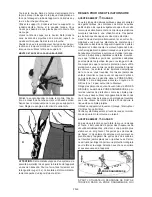
line and cut-off matter is made in the part of the line’s
circular movement, where it is moving AWAY from the
operator and protection cover (see appropriate figure).
This results in caught objects and cut-off matter being
thrown AWAY from the operator.
If the line head rotates in a CLOCKWISE direction, the
LINE CUTTER must be installed on the right side of the
protection cover.
WARNING
DANGER
Tilting the head to the wrong side results in the cut-
off matter being thrown TOWARDS the operator. If
the cutting head is held in a horizontal position to the
ground so that cutting occurs over the whole cutting
circle of the line, cut-off matter will be THROWN at the
operator, the high workload will slow the engine down,
and you will use up a lot of line.
Use only quality nylon monofilament line with a diam-
eter of 2.5mm. Never use wire or wire-reinforced line
instead of nylon trimmer line. Load your nylon cutting
head with nylon trimmer line of the proper diameter
only.
Use extreme caution when cutting over bare spots
and gravel as the line can throw small stones at high
speeds. The protection cover on the unit cannot hold
back objects that bounce back or rebound from hard
surfaces.
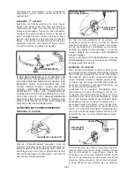
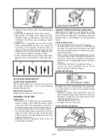
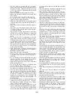
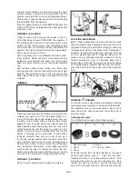
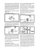
TRIMMEN
KNIFE SIDE RAISED
ANGLE TO GROUND
ANGLE TO WALL
OBJECTS
Trimming means feeding the trimmer carefully into the
material you wish to cut. Tilt the head slightly to di-
rect cut-off matter and caught objects away from you.
If cutting up to a barrier such as a fence, wall or tree,
approach from an angle where any objects bouncing
back from the barrier will fly away from you. Move the
cutting head slowly until the grass is cut right up to the
barrier – but do not push (overfeed) the line into the
barrier. If trimming up to a wire mesh or chain linked
fence be careful to feed only up to wire. If you go to
far the line will get caught and wrap itself around the
wire. Using the trimmer you may also cut through weed
stems one at a time. To do so, place the cutting head
near the bottom of the weed – never higher up as this
could cause the weed to chatter and catch the line.
Rather than cutting the weed right through, just use the
very end of the line to wear through the stem slowly.
WARNING
DANGER
Do not to use a steel blade for edging or scalping.
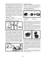
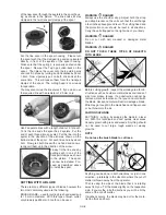
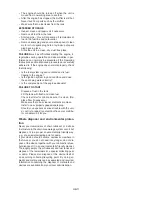
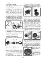
SCALPING AND EDGING
Both of these applications are done with the line head
tilted at a steep angle. Scalping is removing the whole
top growth leaving the earth bare. Edging is trimming
the grass back where it has spread over a sidewalk or
driveway. During both edging and scalping, hold the
unit in a steep angle and in a position where cut-off
matter and any dislodged dirt and stones will not be
thrown towards you, even if it bounces back from a
hard surface. Although the picture shows both edging
and scalping every operator himself must find the an-
gles which suit his/her body size and cutting situation
best.
WARNING
DANGER
Do not trim in areas where there are strands of fencing
wire. Always wear protective clothing and other protec-
tion equipment for your personal safety. Never cut in
areas where you cannot see what the cutting tool is
actually cutting.
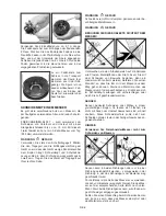
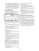
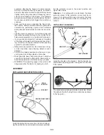
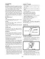
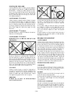
Changing the spool
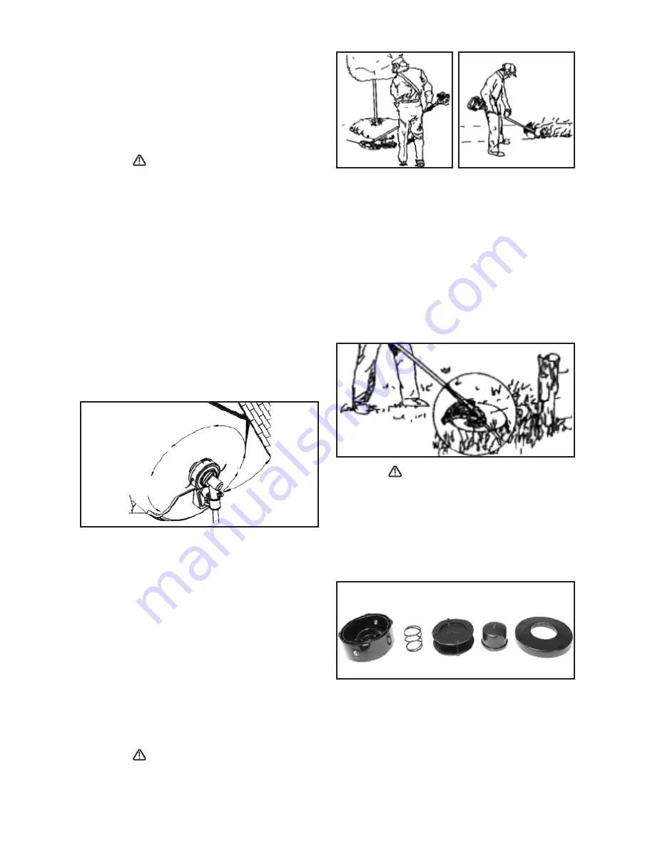
The cutting head consists of the following parts:
2
3
4
5
1
1 Spool housing 2 Spring
3 Spool 4 “Tap’n go” button
5 Cover
Push the locking latch located laterally on the spool
housing (see picture, action 1). Then turn the cover
clockwise by about 1.5 cm (see picture, action 2). This
will unlock the cover 5 and it can be removed. Now
remove the Tap’n go button 4 and then the used-up
spool 3 from
the spool housing. Pass the two line ends
GB-7
Summary of Contents for BT 4344
Page 2: ......
Page 94: ...GR 1 15 ELLHNIKA...
Page 96: ...15 15 GR 3...
Page 97: ...Raynaud GR 4...
Page 98: ...M5xl6 M5x20 M5x25 X 2 X 2 1 1 2 2 2x16 3 A B GR 5...
Page 99: ...A 3 B A S 4 mm 2x16 A B x x GR 6...
Page 100: ...15 16 15 METERS 50 FEET 15 GR 7...
Page 101: ...Monofil 2 5 mm KNIFE SIDE RAISED ANGLE TO GROUND ANGLE TO WALL 2 3 4 5 1 1 2 3 4 5 GR 8...
Page 102: ...1 2 1 5 cm 5 4 3 1 2 2 4 1 5 cm 2 5 mm 2 2 1 m 2 2 cm 15mm 3 255 mm GR 9...
Page 103: ...89 30 1 2 2 30 1 89 30 1 2 30 1 1 2 3 4 3 4 GR 10...
Page 104: ...5 6 1 2 3 4 5 STOPP l Stopp START 2 7 10 CHOKE 3 A 4 5 B 6 7 C A B C 3 7 Stopp STOP GR 11...
Page 105: ...O 6 0 7mm 0 023 O 028 0 6 0 7 mm 145 155 kg cm 1 25 2 GR 12...
Page 106: ...2 GR 13...
Page 107: ...1 0 6 0 7 mm Stop 2 3 0 6 0 7 mm 0 3 0 4 mm 4 GR 14...
Page 108: ......
Page 114: ......
Page 119: ......

