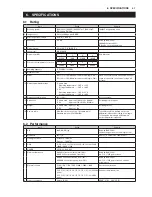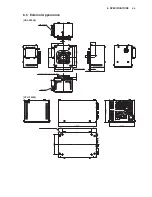
6.6 External
Connectors
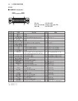
[CAMERA HEAD]
■
Lens Connector
Pin No
Name
Function
I/O
External Interface
(RET ON)
OUT
IRIS SERVO
IRIS CONT
DC+12V output for LENS
Normal operating range : DC + 10 V to + 20 V
OUT
+ 12V LENS
(VTR TRIG)
GND
Ground for lens
Unused
Unused
GND
4
3
2
1
9
8
7
6
5
12
11
10
In
s
ertion Side
4
V
≦
0.5 V
IRIS forced-servo ON/OFF
SERVO ON
SERVO OFF
: + 5 V
±
0.5 V
: 0.5 V or less
Zout = 1000
Ω
Lens IRIS control output
F 2.8
F 16
CLOSE
Zout = 5600
Ω
OUT
IRIS FOLLOW
Lens IRIS control output
F 2.8
F 16
CLOSE
Zin = 95 k
Ω
IN
: 6.2 V
±
0.05 V
: 3.4 V
±
0.05 V
: 2.5 V
±
0.2 V
: 6.2 V
±
0.05 V
: 3.4 V
±
0.05 V
: 2.5 V
±
0.2 V
V = 5 V
±
0.5 V
Camera head
s
ide
Cable
s
ide
: HR10A-10R-12SC
: HR10A-10P-12PC (12 pin male plug)
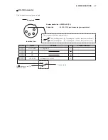
[BTA Mount]
Receptacle
①
②
③
④
⑤
⑥
⑦
⑧
OUT
: + 5 V
±
0.5 V
: 0.5V or less
Zout = 1000
Ω
IRIS REMOTE/AUTO switching
REMOTE
AUTO
IRIS REM/AUTO
8
V
≦
0.5 V
V = 5 V
±
0.5 V
Unused
⑨
⑩
IN
Input and output of ANSWER signal sent from an
external system
IN
OUT
Zin = 33 k
Ω
EXT ANS
: + 0.5 V or less
: OPEN
9
(ZOOM FOLLOW)
V
≦
0.5 V
Unused
Unused
Unused
⑪
⑫
Numbers within parentheses are standard values in the conventional SDTV system of 2/3-inch camera lens.
IN
: camera
←
lens
OUT : camera
→
lens
(FOCUS FOLLOW)
(LENS
→
CAMERA)
(CAMERA
→
LENS)
6. SPECIFICATIONS
6-4
Summary of Contents for HDL-F3000
Page 1: ...3MOS HDTV CAMERA HDL F3000 Operation Manual Products conforming to RoHS directive ...
Page 2: ......
Page 10: ......
Page 12: ...OCP 100 OCP 100 1209 VOL1 J ...
Page 14: ......
Page 20: ......
Page 64: ......
Page 66: ......
Page 68: ......
Page 69: ......

