4.3 Connection of Power Supply
Power supply to the CCU is DC +12V. Its allowable range differs depending on the cable length.
When a lens requiring high power consumption is mounted on the camera head, the camera or lens may not normally operate if the
minimum voltage shown below is underrun due to a voltage drop through the camera cable. Input a higher voltage in such a case
(+16V or lower).
■
'&9WR9ZKHQWKHFDPHUDFDEOHLVPRUVKRUWHU
■
DC +12V to +16V (when the camera cable is 30m or shorter)
CTRL
DC IN
CAMERA
SDI OUT
1
2
REM
WARNING
POWER
CAM
BAR
GAIN
AWB
ABB
H
M
L
G.L IN
G.L
MENU
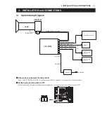
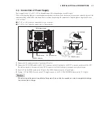
CCU rear view
AC pack
DC POWER cable
DC IN connector
DC OUT
connector
AC outlet
AC connector
POWER
switch
POWER
indicator
POWER switch
POWER indicator
1.
&RQQHFWWKH$&FRQQHFWRURIWKH$&SDFNWRDQ$&RXWOHW
2.
&RQQHFWWKH'&32:(5FDEOHWRWKH'&287FRQQHFWRURQWKH$&SDFNDQGWRWKH'&,1FRQQHFWRURQWKHUHDURIWKH&&8
The cable connector to be connected to the DC IN connector is of latch lock type, so just push it into the connector.
3.
7XUQ³21´WKH32:(5VZLWFKRQWKH$&SDFN7KH32:(5LQGLFDWRURQWKH$&SDFNOLJKWV
4.
Turning “ON” the POWER switch on the CCU supplies power to the CCU. (The POWER indicator on the CCU lights.)
When turning on the power immediately after power-off, do so after two seconds or more to completely discharge
the internal electric charge.
4-3
4. INSTALLATION and CONNECTIONS
Summary of Contents for HDL-F3000
Page 1: ...3MOS HDTV CAMERA HDL F3000 Operation Manual Products conforming to RoHS directive ...
Page 2: ......
Page 10: ......
Page 12: ...OCP 100 OCP 100 1209 VOL1 J ...
Page 14: ......
Page 20: ......
Page 64: ......
Page 66: ......
Page 68: ......
Page 69: ......


