


32
Middle button/wheel:
o
Navigation in the scene to turn the Robot: move the cursor while holding down the
middle mouse button.
o
Mouse wheel: zoom in/out to the current cursor position.
Right key: pan
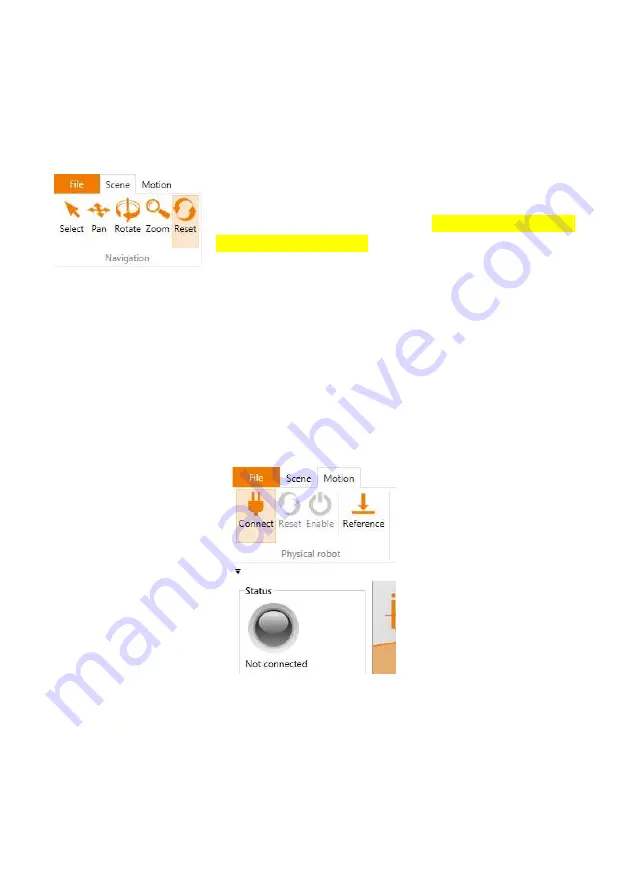
The function of the left mouse button can be changed in the
"Scene" tab under "Navigation" section, with movement options:
"Select", "Pan", "Rotate" and "Zoom". To get back to the initial
starting point click "Reset".
7.2.
Connecting the Robot
7.2.1.
Connection to Hardware
The real Robot can be controlled like the simulated one, only the hardware has to be
connected first by clicking "Connect", "Reset " and "Enable" icons in the "Physical robot"
ribbon group in the "Motion" tab (see Figure 7.3). After that the robot needs to be referenced.
Figure 7.3: Icons for connecting to the hardware, resetting errors and enabling the motors;
referencing icon; and "Status" indicator.
1. "Connect": Establish connection to the hardware.
This step initializes the USB CAN interface or the Ethernet connection.
The "
Status
"
indicator
on the left side changes from grey to red.
Several error messages are displayed below the "Status" indicator.
2. "Reset ": Reset the errors.
Summary of Contents for Drylin Delta
Page 1: ......
Page 2: ...1...
Page 14: ...13 4 Electrical Connections 4 1 Overview Figure 4 1 Overview of electrical connections...
Page 26: ...25 Figure 5 1 Schematic wiring of the safety components with the Support Module...
Page 79: ...78...
Page 80: ...79...
Page 81: ...80...


