


16
4.4.
Pinout: Digital Input/Output Module
The DIO Module provides input and output channels, e.g. to operate a gripper valve. The
outputs can switch up to 500 mA. The inputs use optocouplers and are compatible to input
Voltages between 12 and 24 V.
A circuit switched by the output relays must not contain any larger capacitors.
If the current exceeds 500 mA, the solid-state relays can suffer damage.
For safety reasons, the inputs and outputs of the DIO Module are electrically isolated. This
means that the circuits of the inputs and outputs are not connected to the internal circuits of
the controller.
It is, therefore, necessary to connect a supply voltage for the outputs and a ground line for the
inputs. For this purpose, the 24 V available in the robot controller can be used, but also an
external independent voltage source. In Software the inputs and outputs of the first
DIO Module are numbered 21-27; the second DIO Module (if supplied) has numbers 31-37; and
the third 41-47.
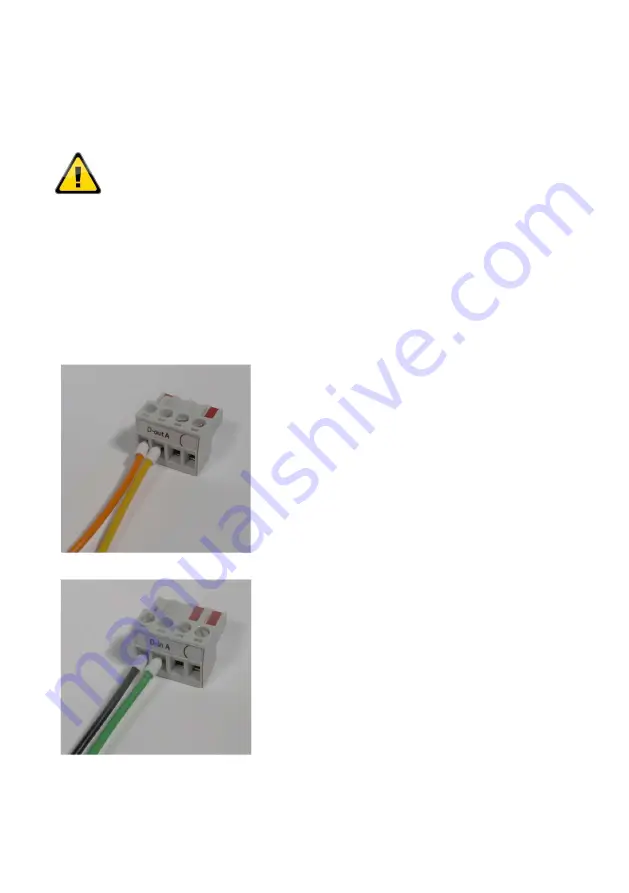
Digital Out connector A (D-out A):
The output relays connect the pin of the power
supply with the corresponding output pins.
Pin 1 (left): Input voltage (for all seven channels)
Pin 2:
D-Out channel 1 (in software: Dout21)
Pin 3:
D-Out channel 2 (in software: Dout22)
Pin 4:
D-Out channel 3 (in software Dout23)
Digital Out connector B (D-out B):
The D-out B pins are (from left to right) the
Digital Out channels 4-7 (picture not shown).
Digital In connector A (D-in A):
Pin 1 of D-In A is the corresponding GND pin for all
input pins.
Pin 1 (left): Signal GND (for all seven channels)
Pin 2:
D-In channel 1 (in software DIn21)
Pin 3:
D-In channel 2 (in software DIn22)
Pin 4:
D-In channel 3 (in software Din23)
Digital In connector B (D-in B):
The D-in B pins are (from left to right) the Digital In
channels 4-7 (picture not shown).
Summary of Contents for Drylin Delta
Page 1: ......
Page 2: ...1...
Page 14: ...13 4 Electrical Connections 4 1 Overview Figure 4 1 Overview of electrical connections...
Page 26: ...25 Figure 5 1 Schematic wiring of the safety components with the Support Module...
Page 79: ...78...
Page 80: ...79...
Page 81: ...80...


