background image

b. 

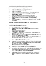
Unit runs unevenly, operating pressure too low or stops even:


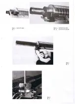
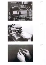
check position of fuel tap (158) (picture 4) 


check diaphragms (104; 105) in air intake valve (101) 


check carburettor gaskets for leakage 


check level in fuel tank 


check, if residues at end of resonator (266) by looking carefully into the  


resonator from a distance of min. 2 m and keep unit running

.  

  Wear 

protective 

goggles


check diaphragms (92) of the valve (90) at air funnel (112) for  


damage and correct seat. At the same time check gaskets (94; 95) 


check swirl vane (116) and mixing chamber (114) for combustion  

  residues 


Adjust fuel dosage (143). Turning counter-clockwise or to the left increases  

  the 

fuel 

flow. 


Attention: Do not unscrew regulating needle (143) too far!   (picture 9)


c. 

If unit generates insufficient fog or none at all:


Decompression screw (59) is not tightened 


Leakage of tank cap (2). Take out gasket (4), turn around or replace if  

  necessary 


Is fog solution socket (57) clogged? 


Is dosage nozzle (250) clogged? 


Feed pressure in solution tank (1) might be too low. Check valves (90) and 
diaphragms (92) for correct seat. 


LED (212) to be checked and if it is not alight, the pressure in the carburettor  


is too low; the solenoid valve cannot open 


Disconnect solution pipe (55) from solution tap (50) and at fog solution socket  


(57) and check solenoid valve (240) for free passage 


Check solution guide system for free passage:


1. 

Loosen solution pipe at the solution tap (50), turn the tap open, solution must  


flow. If not, unscrew filter (45) after loosening glass cap (46) turning counter- 


clockwise, check and clean if necessary. 


Beforehand, decompress solution tank (1)!


2. 

If paragraph 1 is put in order, try again to fog. If without success: 


3. 

Loosen screw of the solution pipe (55) at solenoid valve (240) or hollow screw 
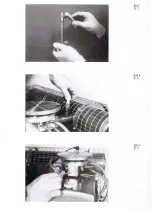
(250) respectively and counterhold with second spanner SW 17 (picture 2).  


Check for solution flow and, if available, assemble again. 


4. 

Loosen hollow screw (250) at solenoid valve (240). After pressing button  


210) and turning solution tap (50) to the position „open“, check if solution  


flows. 


- 11 - 

Summary of Contents for TF 95 HD

Page 1: ...TF 95 HD TF W 95 HD Instructions manual Thermal Fog Generator DIN EN ISO 9001 2008...

Page 2: ...DIN EN ISO 9001 2008 DIN EN ISO 9001 2008 DIN EN ISO 9001 2008 DIN EN ISO 9001 2008 DIN EN ISO 9001 2008 DIN EN ISO 9001 2008 DIN EN ISO 9001 2008 DIN EN ISO 9001 2008 DIN EN ISO 9001 2008 DIN EN ISO...

Page 3: ...ben IGEBA Thermalnebelger te und ULV Aero solgeneratoren werden ausschlie lich in der Bundesrepublik Deutschland von der Firma IGEBA Geraetebau GmbH hergestellt Origi nal IGEBA Erzeugnisse sind mit ei...

Page 4: ...Germany Telefon 49 0 8375 92 00 0 Telefax 49 0 8375 92 00 22 eMail info igeba de Internet www igeba de Stand 01 2013 Die Anleitung ist urheberrechtlich gesch tzt Die dadurch begr ndeten Rechte insbeso...

Page 5: ...e following data Manufacturer s data fog generator model serial number year of construction F r jedes gelieferte IGEBA Erzeugnis leistet die Firma IGEBA Geraetebau GmbH im Rah men der Vertrags und Lie...

Page 6: ...nal zug ng lich halten F r Sch den und Betriebsst rungen die sich aus der Nichtbeachtung dieser Betriebsanlei tung ergeben bernimmt die IGEBA Geraete bau GmbH keine Haftung und keine Gew hr leistungsp...

Page 7: ...06 42 EG Machines standard 2006 42 EG Niederspannungsrichtlinie 2006 95 EG Low Voltage directive 2006 95 EG Elektromagnetische Vertr glichkeit 2004 108 EG Electromagnetic compatibility 2004 108 EG fol...

Page 8: ...Vernebelung von brennbaren Fl ssigkeiten in geschlossenen R umen ist absolut verboten Hinweise in der Bedienungsanleitung 3 Den Dosierhinweisen der Mittelhersteller ist Folge zu leisten Attention 1 Th...

Page 9: ...hren Erg nzend zur Betriebsanleitung sind die am Einsatzort allgemeing ltigen gesetzlichen und sonstigen verbindlichen Regelungen zur Unfallverh tung und zum Umweltschutz zu beachten und anzuwenden Si...

Page 10: ...eseitigen lassen Ein und Ausschaltvorg nge Kontrollanzei gen gem Betriebsanleitung beachten Personen mit Herzschrittmachern d rfen das Ger t nicht bedienen ber hren Any personnel working with the fog...

Page 11: ...r be used against people farm animals or pets The device must not be operated under the influence of alcohol medicine or drugs Furthermore objects body parts animals etc must not be inserted in the op...

Page 12: ...icular for children and persons who are not familiar with it Arbeits und Betriebsverfahren die genau einzuhalten sind um Besch digungen oder Zerst rungen am Nebelger t zu vermeiden Bedienungsanleitung...

Page 13: ...sorgung zu gew hrleisten Bei technischen Problemen die in dieser An leitung nicht angesprochen sind steht Ihnen der Kundendienst Telefon 49 0 8375 9200 0 zur Verf gung sowie Ihr pers nlicher H nd ler...

Page 14: ...on Very hot Dot not touch Risk of burn Hazards Die mit der Bedienung des Ger tes betrauten Personen m ssen sich vor der Inbetriebnahme des Ger tes mit den Sicherheitsma nahmen vertraut machen Das Ger...

Page 15: ...the specifications of manu facturers regarding safety instructions and dosage of formulations Do not spill solution when filling the solution tank Use the IGEBA funnel with strainer Nach Abstellen de...

Page 16: ...the heat deflector shield heat up due to tempe rature radiation Avoid touching those parts Falls Sie Wirkstoffbr he beim Einf llen versch tten wischen Sie die Br he ab Bei tzenden Wirkstoffbr hen mu...

Page 17: ...try specific regulations as well as the guidelines of the agent manufacturer 17 F hren Sie Reparaturen nur am abge k hlten Ger t aus Nach Reparaturarbeiten zuvor entfernte Schutzvorrichtungen wieder a...

Page 18: ...nger of burn burning by stumble 31 Walking direction should be contrary to the fogging direction Pay attention to suffici ent sight 24 Stellen Sie sicher da ein Feuerl scher zur Verf gung steht bevor...

Page 19: ...fo igeba de www igeba de DIN EN ISO 9001 2008 DIN EN ISO 9001 2008 DIN EN ISO 9001 2008 DIN EN ISO 9001 2008 DIN EN ISO 9001 2008 DIN EN ISO 9001 2008 DIN EN ISO 9001 2008 DIN EN ISO 9001 2008 DIN EN...

Page 20: ...SPARE PARTS LIST Summary Page 1 Mode of operation 2 2 Technical specifications accessories 3 3 Instruction manual 5 3 1 Readying unit for use 5 3 2 Starting the unit 7 3 3 Stopping the unit 8 3 4 Aut...

Page 21: ......

Page 22: ...mer hinterlegt Mit der Pos Nr im Text und mit Hilfe der Explosionszeichnung ist eine eindeutige begriffliche Zuordnung in der vorliegenden Bedienungsanleitung gegeben Bei Ersatzteilbestellungen unbedi...

Page 23: ...ially with all risks and safety precautions in order to avoid damage Risks for persons and environment could arise out of faulty operation and out of forbidden fields of application Damages due to fau...

Page 24: ...rf llt in der ausgelieferten Ausf hrung die Anforderungen der EG Richtlinien 89 336 EWG Elektromagnetische Vertr glichkeit und der Maschinenrechtlinien 2006 95 EG The shipped version of this device co...

Page 25: ...Schutzbrille und Schutzhandschuhe tragen Entsorgen Sie Reste von Wirkstoffbr hen immer ordnungsgem Befolgen Sie die rechtlichen Vorschriften hinsichtlich Lagerung und Entsorgung der Wirkstoffe 1 The...

Page 26: ...of the unit Carry the belt at the same shoulder side which has to carry the unit That means do not put the belt over your neck Only TF W60 16 Do not touch hot areas of the unit because touching leads...

Page 27: ...evocol 1 5 l b Kraftstoffe Wei le Pflanzen le 2 5 l Diesel Heiz le 2 0 l Petroleum 2 0 l Petropal 2 0 l Shell Risella 15 1 5 l 24 Make sure that a fire extinguisher is available before you start worki...

Page 28: ...und ohne Aufsicht l uft mu es mit Wirkstoff notabschaltung ausger stet sein Though these values may not correspond with those given by the manufactures and may be higher than limits quoted in dosage...

Page 29: ...xecution TF W 95 HD M with automatic cut off device solenoid valve Standard accessories 1 set of flow control nozzles 1 4 abt 30 l h 1 2 abt 20 l h measurements taken applying 2 0 abt 50 l h 1 4 abt 3...

Page 30: ...00 00 X X Pressure gauge 0 250 mbar to control pressure in fuel tank Nr 11 40 000 00 X X Turn table for horizontal rotation of the unit Nr 11 11 000 00 X X 1 set of special tools for maintenance Nr 11...

Page 31: ...d solution tap 50 before every transportation 3 1 Readying unit for use For transportation fog tube 260 is not in proper position for fogging when unpacked picture 3 This is not applicable when TF W 9...

Page 32: ...essing red button 211 and the green light diode 212 must illuminate Check ignition Check ignition coil by pressing the starter switch 195 and a buzzing sound should be audible Preferably the air filte...

Page 33: ...4 Agitate starting air pump 82 by pressing starter button 195 a the same time Comment When starting the unit everything depends on an even pumping action If unit is cold pump smoothly and if unit is...

Page 34: ...as as mentioned above except of TF W 95 HD two alternatives to stop the solution output a solution tap 50 and b solenoid valve 240 Press the red button 211 to shortly interrupt the fogging operation s...

Page 35: ...socket 57 and collect the cleaning agent in a container To ensure that your fog generator is ready for use at any time we recommend before storage a Rinse empty solution tank 1 and clean same as desc...

Page 36: ...04 105 in air intake valve 101 Remove swirl vane 116 and clean if necessary picture 7 Check fuel flow Unscrew dosage needle 143 and check whilst activating air pump 82 if fuel appears at bore of housi...

Page 37: ...on socket 57 clogged Is dosage nozzle 250 clogged Feed pressure in solution tank 1 might be too low Check valves 90 and diaphragms 92 for correct seat LED 212 to be checked and if it is not alight the...

Page 38: ...tive switch 214 is defect If however the LED shows green but no sound is audible the battery voltage is too low less than 4 volts or the core 243 in the solenoid valve 240 is stuck To dismantle soleno...

Page 39: ......

Page 40: ......

Page 41: ......

Reviews: