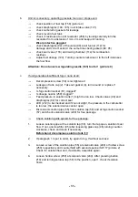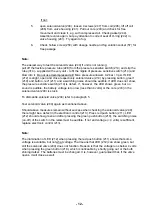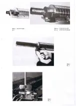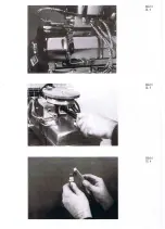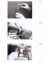
Mount air filter as follows:
-
Unscrew fillister head screw (155), holding tight centering bar (179)
-
Screw on centering bar (179) by hand to valve plate (102) of the air intake valve and
tighten with spanner by about ¼ turn, but not too tight!
-
Push hood (176) with insert (178) over centering bar (179)
-
Screw in and tighten screw (155)
Insert batteries
-
Lift off control box (186;187) after loosening wing screws (2+1 pieces) (188) and
insert 4 mono cells IEC R 20, 1,5 V, in to battery holder (189) and follow given
sequence. Check for contact by pressing red button (211) and LED (212) must
illuminate.
Attention:
Use only fresh batteries. The electronic solution control needs a minimum of 4,5 Volts
under load in order to guarantee proper functioning. Batteries can be checked by
pressing red button (211) and the green light diode (212) must illuminate.
Check ignition:
Check ignition coil by pressing the starter switch (195) and a buzzing sound should
be audible. Preferably the air filter should not be mounted.
Fill fuel tank:
Adjust fog tube (260) to horizontal position. Always use the funnel with strainer.
Regular fuel is sufficient. Tighten tank cap (152). Do not spill fuel over carburettor.
Fill solution tank:
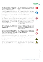
Always use funnel (large) with strainer! Before filling, check if solution tap (50) is
closed (refer to label [6]). Tighten tank cap (2). Control, if decompression valve (59)
is tightened to the right side and fully closed.
Select fog solution output:
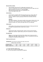
ATTENTION:
Flow control jet is pressed into hollow screw (250).
Hollow screws are marked.
Dosage
nozzle
12* 14 16 20**
27**
55**
approx.
output
in
l/h 20 30 40 50 70 100
(* = for water based formulations only)
(55 = hollow screw only without dosage nozzle)
(** = don’t use these nozzles for water based formulations)
- 6 -
Summary of Contents for TF 95 HD
Page 1: ...TF 95 HD TF W 95 HD Instructions manual Thermal Fog Generator DIN EN ISO 9001 2008...
Page 21: ......
Page 39: ......
Page 40: ......
Page 41: ......

