The function and mode of operation of the automatic cut-off device - consisting off: pressure
control in carburettor, solenoid valve and control system - are explained as following:
The carburettor system and the fuel tank have a certain pressure range when unit is warm
which fluctuates only negligibly. Any kind of problems, e.g. lack of fuel, clogging of the
resonator due to solution deposits, have a substantial effect on the pressure sensitive switch
(214) over the pressure line (228) through which the solenoid valve (240) is closed by an
electronic control (213) to warrant that no solution flows uncontrolled into the resonator (266).
Thus fire hazard is not existing.
Note:
The pressure sensitive switch (214) should not be touched as the switch has been set
in the factory already.
4.
Cleaning the unit
At least once a week all solution carrying pipes should be cleaned. When using water as a
carrier, this should be done after every operation. Pour 1-2 litres of diesel oil or water into the
solution tank and fog to clean the pipe system in general. If fogging is not possible, unscrew
hollow screw (250) at the fog solution socket (57) and collect the cleaning agent in a
container.
To ensure that your fog generator is ready for use at any time, we recommend before
storage:
a.
Rinse empty solution tank (1) and clean same as described before.
b.
Empty fuel tank (151) after loosening hollow screw with filter (164) whilst tank cap
(152) has been opened and fog tube (260) pointing upwards and fuel tap (158)
opened.
c.
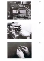
Take off hood (176), pull out filter insert (178) and check if clean. Dismantle air
intake valve (101) to check diaphragms:
→
unscrew centering bar (179)
→
loosen nut (17) counterholding from underneath at screw (107) with screwdriver for
recessed-head screws supplied with unit.
→
take off valve plate (102), check diaphragms (104; 105) for dirt, but do not loose
rubber gasket (103). If necessary, clean valve, e.g. with a fuel soaked cloth.
Diaphragms must be absolutely plane and free from creases.
d.
Clean unit of any dirt.
e.
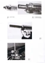
Remove residues at end of resonator (266), in fog solution socket (57), at the inner
side of the fog tube (260) and at adapter (261) respectively with the tool supplied
(332) and blow through with compressed air if possible, e.g. when air intake valve is
dismantled blow into air funnel (112).
f.
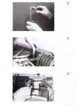
Clean carburettor, mixing chamber (114) and mixing tube after removing swirl vane
(116) with the pipe cleaning tool (332) after having unscrewed spark plug (201).
- 9 -
Summary of Contents for TF 95 HD
Page 1: ...TF 95 HD TF W 95 HD Instructions manual Thermal Fog Generator DIN EN ISO 9001 2008...
Page 21: ......
Page 39: ......
Page 40: ......
Page 41: ......

